


E-15
Parts and functions (Continued)
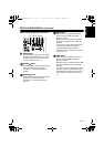
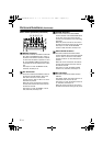
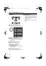
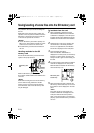
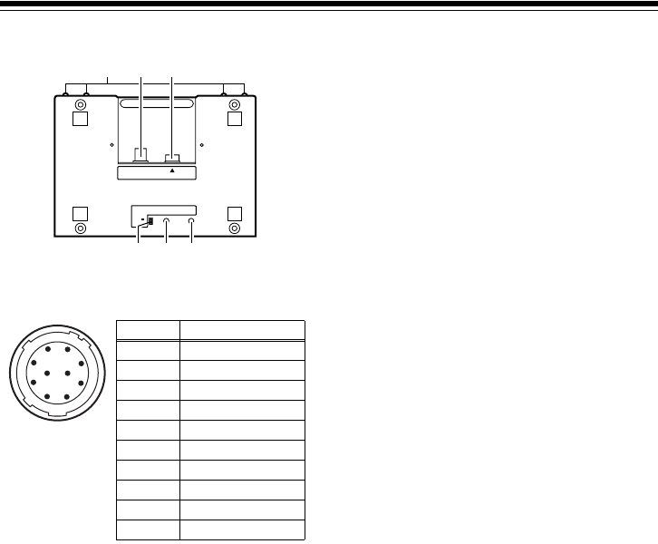
Rear panel
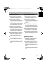
!1" Camera connection connector
To connect the 10-pin camera control cable.
!2" VIDEO OUT connector
An NTSC or PAL monitor is connected for
operating the menu on the main unit of the
camera recorder.
!3" Cable length selector switch
This switch is on for a 50 m cable.
!4" Frequency characteristics
adjustment volume
This adjusts the frequency characteristics of
the VIDEO signals.
!5" Level adjustment volume
This adjusts the level of the VIDEO signals.
!6" Covering screw
The unit can be used when the four screws
are removed. However, do not leave the unit
without these screws for long periods of
time. When the screws are not in use, they
must be stored safely.
<Note>
Do not remove the four screws on the back
panel.
!2"
!1"
VIDEO OUT
CAM RCU
50m
10m
CABLE
FREQUENCY LEVEL
!4"
!3"
!5"
!6"
1
2
3
4
5
6
7
8
910
Pin No. Signal
1CAM DATA (H)
2CAM DATA (C)
3 CAM CONT (H)
4 CAM CONT (L)
5 ECU_ON
6Video input
7 GND (Video)
8 Standby
9+12 V (IN)
10 GND
AJ-RC10G(VQT1A65-1).book 15 ページ 2007年2月14日 水曜日 午後4時16分