


16
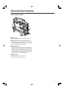
Shooting (recording)/playback
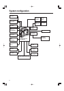
function section (3)
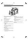
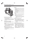
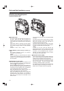
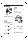
7SHUTTER switch
This is set to ON when the electronic shutter is to
be used. When the SEL side is pressed, the
shutter speed and mode display are changed in the
range which was set ahead of time in the setting
menu.
If this switch setting is changed while the display
mode is set to “2” or “3,” the new setting will appear
at the shutter display position on the viewfinder
screen.
(Example: “: 1/120”, “: 50%”, “: 180d”)
8ECU REMOTE (remote control) connector (6-
pin)
The AJ-EC3 extension control unit (optional
accessory) is connected here.
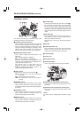
<Note>
Before connecting or disconnecting the remote
control cable, be absolutely sure to set the POWER
switches on the unit and extension control unit to
the OFF position.
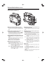
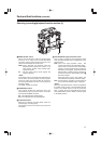
9HD SDI MON connector (BNC)
The HD SDI signals (video and audio) for the
monitor in accord with the position of the MONITOR
OUT switch ; are output from here.
When the MONITOR OUT switch is at “EE/PB,” the
EE video and EE audio signals will be output during
recording and the playback video and playback
audio signals will be output during playback.
When the MONITOR OUT switch is at “EE,” the
camera video signals are output at all times.
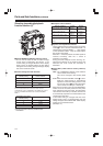
When the CHARACTER switch is set to ON while
performing the menu settings, it is possible to
superimpose the setting menus onto the pictures
being shot so that they can be checked on the
monitor screen.
The user bits are also output from the HD SDI MON
connector.
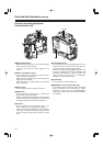
The active frame count is output to the four higher
digits of the user bits. The count is reset to zero
each time recording starts, and the count is
incremented with each active frame.
The active frame information is output to the lowest
digit of the user bits while the frame rate information
is output to the third and fourth lower digits.
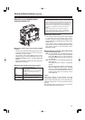
<Note>
In order for the time code that matches the
playback time code, which is output from the HD
SDI MON connector, to be output from the TC OUT
connector, set the MONITOR OUT switch to
“EE/PB,” and select “TCG/TCR” as the TC OUT
item setting on the TC/UB screen.
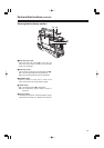
:HD SDI EE connector (BNC)
The HD SDI camera signals are always output from
here. No menu items are contained in the output
signals which are supplied from this connector.
The active frame information is allocated to the user
bits in the time code data in the signals and output
from the connector. Use this connector when
connecting a backup recorder for recording.
The images may be disrupted when the frame rate
has been changed or recording has started. For
details, refer to “Variable frame rate” (page 63).
Parts and their functions (continued)
:
79
8