


5
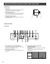
MAJOR OPERATING CONTROLS AND THEIR FUNCTIONS
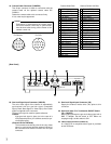
Camera Head
1. Lens Mount
This is used to attach the special C-mount lens for GP-
US522 and the C-mount lens for GP-US532.
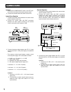
2. Camera Cable Connector
This 24-pin connector is used to connect the optional
camera cable GP-CA522/4 to the camera control unit.
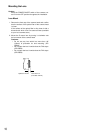
3. Camera Mounting Screw Hole
This hole (1/4" - 20) is used to mount the camera onto
a mounting bracket.
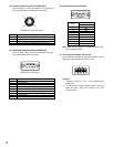
4. Power ON/OFF Switch (DC POWER ON/OFF)
This switch turns the power of this unit and the power
supply for the camera head on or off.
5. Power Indicator (POWER)
This indicator lights up red when the power switch is
turned on.
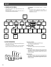
6. Automatic/Manual Gain Selector Switch
(GAIN HIGH/LOW/OFF)
This selector is used to select the gain of video amplifi-
er as follows.
The mode can be selected in the SET UP menu.
Refer to page 16.
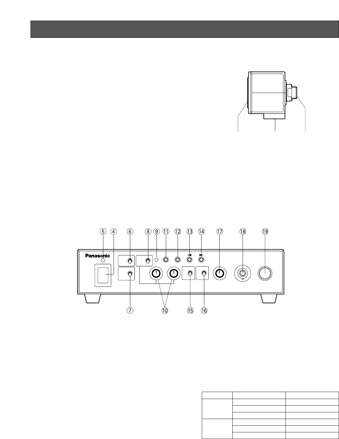
Camera Control Unit
[Front Panel]
MODE POSITION OF SW GAIN
HIGH Maximum +18 dB
AUTO LOW Maximum + 9 dB
OFF 0 dB
HIGH +18 dB (Fixed)
MANU LOW +9 dB (Fixed)
OFF 0 dB
q e w
CAM
HIGH
ATW
MANU
LOW
OFF
BAR
R B
1
2
SCENE
ON
OFF
ELC
LEVEL TITLE CAMERA
PAGE ITEM
(AWC) (ABC)
GAIN
DC POWER
ON
OFF
AWC
Camera Control Unit
GP-
US522
GAIN