


8
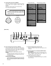
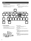
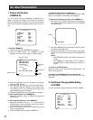
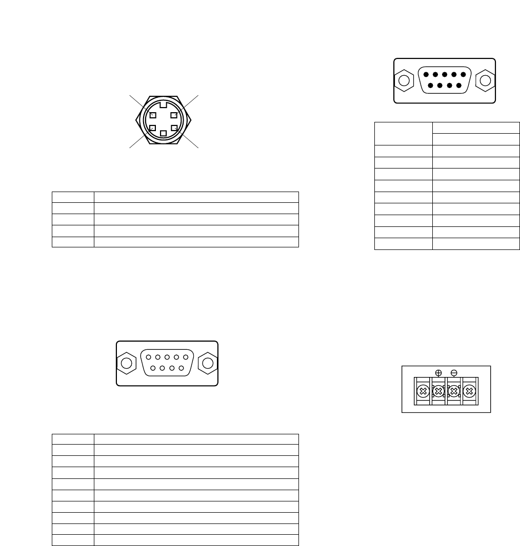
S-VIDEO OUT (Mini-DIN,4-pin)
Pin No. Description
1 Y Ground
2 C Ground
3 Y Signal Output (0.714V[p-p](Y level)/75 Ω)
4 C Signal Output (0.286V[p-p](Burst Level)/75 Ω)
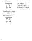
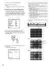
25. RGB/SYNC Output Connector (RGB/SYNC)
The red, green, blue, sync and composite video sig-
nals are provided at this connector.
RGB/SYNC (D-SUB,9-pin)
Pin No. Description
1 Ground( GND)
2 Ground (GND)
3 Red (R) Output (0.7V[p-p]/75 Ω)
4 Green (G) Output (0.7V[p-p]/75 Ω)
5 Blue (B) Output (0.7V[p-p]/75 Ω)
6 Composite Video Output (1.0V[p-p]/75 Ω)
7 Sync (SYNC) Output (4.0V[p-p] or 0.3V[p-p]/75 Ω)
8 Ground (GND)
9 Ground (GND)
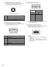
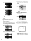
26. RS-232C Connector (RS-232C)
Pin No
Signal
RS-232C
Ground
TXD
RXD
DSR
Ground
DTR
CTS
RTS
Ground
1
2
3
4
5
6
7
8
9
24. S-Video Output Connector (S-VIDEO OUT)
The luminance (Y) and chrominance (C) signals for
VCR or monitor are provided at this connector.
43
21
51
96
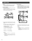
Note: Refer this connection to a qualified service par-
son or system installer.
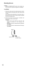
27. 12V DC Input Terminals (12V DC IN)
These terminals accept an external DC power source
supplying nominal power of 12V DC, 0.7A.
Cautions :
1. Connect to 12V DC (11.5 V - 16 V) class 2 power
supply only.
2. To prevent fire or electric shock hazard, use a UL
listed wire VW-1, Style 1007 cable for 12 V DC
input terminals.
15
69