


7
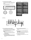
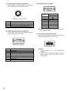
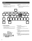
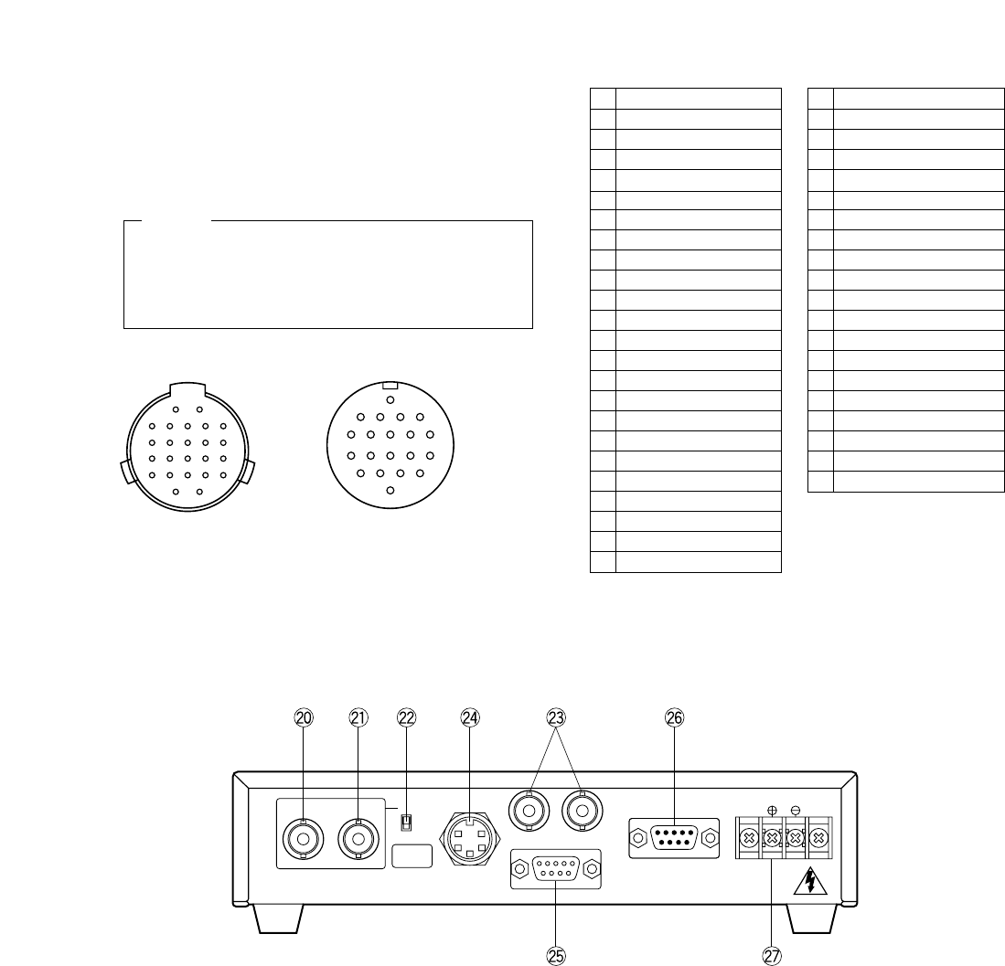
Camera Head Side Camera Control Unit Side
1 +15V Input
2 Ground (GND)
3 Chip Select Input
4 +25 Input
5 −9V Input
6 B Signal Output
7 RGB Ground (GND)
8 Serial Data Input
9 Serial Clock Input
10 CCD Select Output
11 G Signal Output
12 R Signal Output
13 VD Input
14 CPOB Output
15 HD Input
16 +9V Input
17 +5V Input
18 PBLK Output
19 Not used
20 Not used
21 Not used
22 Not used
23 28MHz Input
24 Not used
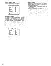
1 Ground (GND)
2 Not used
3 PBLK Input
4 +9V Output
5 −9V Output
6 28MHz Output
7 CPOB Input
8 RGB Ground (GND)
9 +5V Output
10 B Signal Input
11 Serial Clock Output
12 VD Output
13 Chip Select Output
14 +25 Output
15 R Signal Input
16 Serial Data Output
17 HD Output
18 G Signal Input
19 +15V Output
20 CCD Select Input
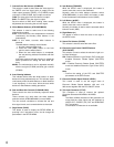
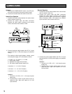
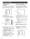
19. Camera Cable Connector (CAMERA)
This 20-pin connector is used for connection with the
camera head via the optional camera cable GP-
CA522/4.
Fasten the camera cable to this connector firmly.
If not, noise may be appeared.
20. Gen-lock Signal Input Connector (VBS/HD)
The color video signal of the camera is automatically
synchronized with the gen-lock signal (Composite
Signal, Black Burst Signal or Video Sync) when either
signal is supplied to this connector.
The gen-lock signal is used for system reference.
Caution :
If the gen-lock signal is jittery (as in the case of a
VCR playback picture), the camera cannot be syn-
chronized properly.
(External HD and VD Mode)
The horizontal and vertical pulse of the color video
signal is synchronized with the external HD fed to
this connector and external VD fed to the VD input
connector.
21. Gen-Lock Signal Input Connector (VD)
Supply the external vertical drive (VD) pulse to this
connector.
22. Gen-Lock Video 75 Ω Termination ON/OFF Switch
(75 Ω ON/OFF)
When looping through the gen-lock video signal with a
BNC "T" adapter, set this switch to OFF. When not
looping through, set this switch to ON.
23. Video Output Connector (VIDEO 1,2)
A 1.0V[p-p]/75 Ω composite video signal is provided
at this connector.
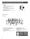
[Rear Panel]
For Camera
VBS/HD VD
OFF
ON
75Ω
S-VIDEO
OUT
1 2VIDEO
RS-232C
RGB/SYNC
DC 12V IN
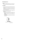
Connecting or disconnecting the camera cable
to/from the camera control unit or camera head
must be done after turning off the Power of the
camera control unit.
Caution
1
2
5
6
10
1511
19
20
16
For CCU
2122
15
20
24 23
2
1
1617
101112
567
1819
1314
89
34