


C2462M-D (3/08) 13
INSTALLATION TO THE SURFACE OF A 4S STANDARD
ELECTRICAL BOX
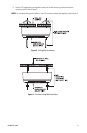
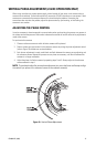
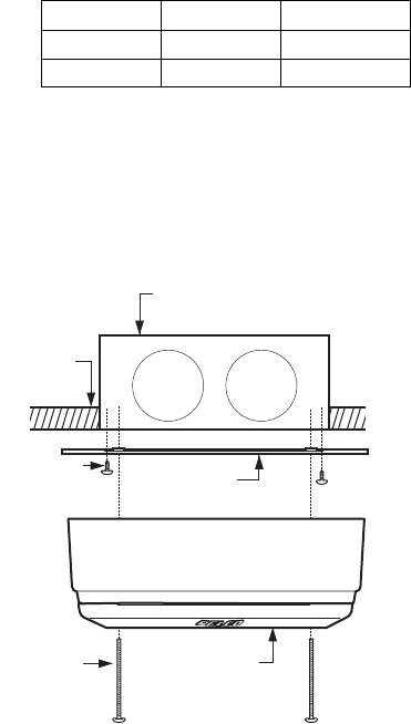
Refer to Figure 7 and complete the following steps.
1. Attach the adapter ring to the 4S box with the two 8-32 x 1.00-inch screws (supplied).
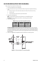
2. Connect the video cable/wires.
BNC: Connect the BNC connector from the Camclosure to a mating BNC connector.
Twisted pair: Connect the blue wire to Video +; connect the gray wire to Video -.
3. Connect the power wires.
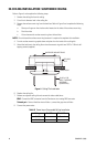
AC Operation Only: If you are wiring more than one ICS090 Camclosure to the same transformer,
connect one side of the transformer to the red wire on all units, and then connect the other side of the
transformer to the black wire on all units. Failure to connect all of the units in the same way will cause
the cameras to be out of phase with each other, which might produce a vertical roll when switching
between cameras.
4. Attach the surface trim ring and back box to the adapter plate with the two 8-32 x 2.50-inch screws
(supplied).
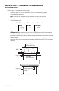
Figure 7. 4S Standard Electrical Box Installation
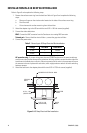
Table D. Power Input: 4S Standard Electrical Box Installation
Voltage Red Wire Black Wire
12 VDC + Ground
24 VAC ~ ~
CEILING/
WALL
4S STANDARD
ELECTRICAL BOX
OPTIONAL
ADAPTER RING
8-32 X 1.00
(SUPPLIED)
BACK BOX AND
SURFACE MOUNT
RING
8-32 X 2.50
(SUPPLIED)