C1640M-B (3/06) 11
USING TTL TO CONTROL NETWORK TRAFFIC IN BROADCAST DOMAINS
In the Endura network, TTL is used to set the maximum amount of router hops that a packet is allowed to propagate through the network before
the packet is discarded. Using TTL provides an effective method to determine how many broadcast domains a given packet can traverse.
• For Endura components (excluding the SM5000), the default TTL settings are as follows:
– UPnP traffic: The TTL is set to 1. In this case, each block is assigned to a specific VLAN, keeping UPnP traffic isolated within that block
(refer to Figure 3).
– Video packets: The TTL is set to 3 so that the video packets can traverse the entire network.
• For the SM5000 in the Core Block, the default TTL setting is 4. In this case, the SM5000 Locator broadcasts can traverse across
subnetworks to discover Endura components.
This approach ensures that two networking functions be efficiently accomplished:
• Each NVR5100 only records video streams from encoders from which it sees in its block. The NVR5100 sends a query with a TTL of 1, which
means it will only discover devices on its VLAN.
• Unnecessary traffic is eliminated from traversing across the Core Block.
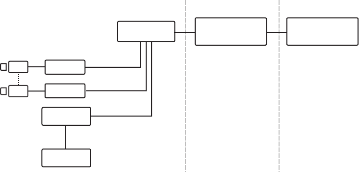
Figure 3 illustrates how the broadcast traffic is localized to A Block 1 in broadcast domain 1. In this case, the broadcast traffic from VLAN 1 never
traverses the network because TTL is decremented to 0 at the core switch and the packet is dropped.
Figure 3. TTL Is Set to 1 in VLAN 2 and Keeps UPnP Traffic Within the A Block
LAYER 2 SWITCH
NVR
SEB
ENCODER
ENCODER
VLAN 3, TTL=1
VLAN 3, TTL=1
VLAN 3, TTL=1
A BLOCK
VLAN 3
CORE SWITCH
VLAN 1
TTL = 0
B BLOCK
VLAN 5
