Pelco Manual C466M-E (6/99) 23
5.3.2 Addressing
The address is set on the CPU board PCB8500110. The switch is labeled SW1.
Setting the switch in the “ON” position represents a zero. The first five positions set
the receiver address (1 through 5) from a range of 0 to 31. The last three (6 through 8)
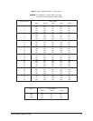
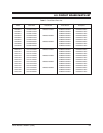
set the baud rate. Refer to Table B.
SW1.1 — Address Bit 0
SW1.2 — Address Bit 1
SW1.3 — Address Bit 2
SW1.4 — Address Bit 3
SW1.5 — Address Bit 4
SW1.6 — 9600 Baud
SW1.7 — 4800 Baud
SW1.8 — 2400 Baud
5.3.3 Receiver Cards
The RS-422 style Intercept
®
receivers use only two of the three receiver cards.
There must be a power supply (either AC or DC) and a CPU card. The video card is
not used. Therefore the camera video output is connected directly to the slip ring.
This eliminates the dome’s ability to superimpose text on the video. This eliminates
any label and zone feature. If these features are needed additional firmware will be
needed.
5.3.4 Commands
Commands are divided into two (2) categories. The first is referred to as PTZ com-
mands. The second category is Extended commands. The paragraphs below de-
scribe their functions.
5.3.4.1 PTZ (Pan/Tilt and Zoom) Commands
PTZ commands will always have B0 of word 4 set to zero. The remainder of the
format is as follows.
Word 3 B7 — Always Zero (was camera on, auto scan)
B6 — Camera On (was Coaxitron usage only)
B5 — Auto Scan On (was Coaxitron only)
B4 — Camera On, Camera Off (was auto scan, manual scan)
B3 — Iris Close
B2 — Iris Open
B1 — Focus Near
B0 — Focus Far
Word 4 B7 — Always Zero
B6 — Zoom Wide
B5 — Zoom Tele
B4 — Down
B3 — Up
B2 — Left
B1 — Right
B0 — Always Zero for PTZ command
Word 5 Pan speed with values 0 to 0x3F and 0xx40 (Pan Turbo)
Word 6 Tilt speed with values 0 to 0x3F


