Pelco Manual C480M-F (10/04) 7
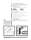
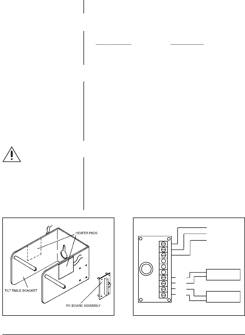
Figure 4. HK8000/HK8024 Heater Kit Installation Figure 5. HK8000/HK8024 Heater Kit Wiring Diagram
1
2
3
4
5
6
7
8
9
AC HI INPUT
AC NT INPUT
GROUND
HEATER
40 WATTS
HEATER
40 WATTS
WHT
WHT
WHT
WHT
10
3.5 OPTIONAL HK8000/HK8024 HEATER KITS
The HK8000 and HK8024 Heater Kits require 120 VAC or 24 VAC respectively, and
both provide 80 watts of heat which is thermostatically controlled to activate at 40°
F and turn off at 60° F
3.5.1 Recommended Cable Size
The following cable sizes are the minimum recommended for use with heater kits.
120 VAC Operation 24 VAC Operation
22 Awg to 400 ft (121.9 m) 20 Awg to 35 ft (10.7 m)
20 Awg to 650 ft (198.12 m) 18 Awg to 60 ft (18.3 m)
18 Awg to 1,100 ft (335.3 m) 16 Awg to 80 ft (24.4 m)
3.5.2 Heater Kit Installation
To install the HK8000/HK8024, perform the following steps (refer to Figure 4):
1. Open the cover.
2. Attach the heater pads to each side of the tilt table bracket.
3. Press the PC board assembly into the four (4) holes provided in the tilt table
bracket.
4. Wire according to the diagram shown in Figure 5.
5. Close and lock the cover.
3.6 ELECTRICAL CONNECTION
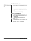
After the cable has been routed, all wire connections should be made (i.e., video,
lens, camera power, heaters). A 6-position terminal block has been provided to
assist in this.
CAUTION:
When a single power
source is used for both the camera
and accessories, the camera power
consumption must be taken into con-
sideration when determining the wire
gauge. Also, make certain that all
electrical connections are done prop-
erly and meet electrical codes.


