


2.3.4 How to use the isolated input/output
In this part the user will find how the optical isolation is
implemented in the Inca. Not only the digital input and
output lines are optically isolated but also the flash and
watchdog output and the trigger input.
Page 8 2005-12-12
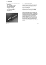
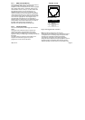
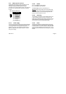
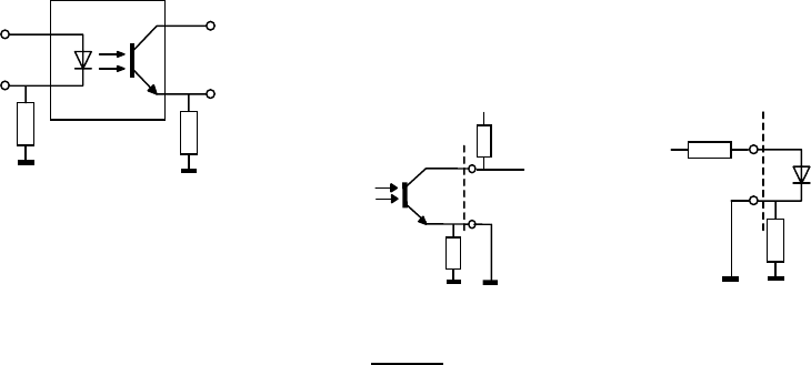
Figure 2-4: Circuit for optical isolation
The above circuit is the one used in the camera. Hereafter
will be explained how these circuitry can be used by the
user of the Inca.
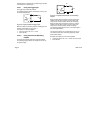
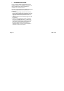
2.3.4.1 INPUT
As already mentioned in paragraph 2.3.3 Digital I/O the
input current for Ion is between 6.3 mA and 10 mA. Ion is
the current whereby the output transistor is conducting. In
order to prevent the input from left floating, the return (n) is
internally connected with a high impedance to ground. In
order to let the input functioning properly the user must
connect the common ground to the signal ground.
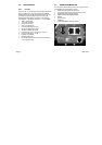
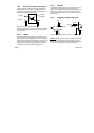
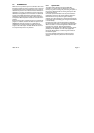
2.3.4.2 OUTPUT
The optically isolated output is only a transistor. As can be
seen in figure: 2-6 the emitter is connected via a 1M
resistor to ground. It prevents the output transistor from left
floating. If the output is conducting the output current Ion
must be in the range 0.9 mA < Ion < 18 mA. The maximum
Vce is 40 volt.
Inverting
output(p)
Input(p)
2.3.4.3 Suggestion for Output and Input :
Return
(
n
)
24V
Warning:
Writing a True or One to the digital output results
in an Ioff (out = high because of pull-up resistor), on the
contrary writing a False or Zero to the Digital output results
in a Ion (out = low because of transistor short circuit).
1M
1M
2K7
2K7
24V input
User side
Out si
g
nal
User
1M
1M
Fi
g
ure 2-6: O
p
to-isolated out
p
ut Fi
g
ure 2-5: O
p
to-isolated in
p
ut