


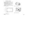
2.3.3 Digital I/O
The Digital Input and Output connectors give the user
the possibility to connect and control a number of devices.
For that purpose 6 output and 6 input lines are available.
These output and input lines are optically isolated from the
Inca (see explanation: 2.3.4 How to use the isolated
input/output).
Input 6 differs from the other inputs in a way that it has a
special purpose. Input 6 can be used as an interrupt input
either level or edge sensitive.
All inputs and outputs are TTL level compatible.
• input current 6.3 mA < Ion < 10 mA
• Pmax 20 mW
• output current 0.9 mA < Ion < 18 mA, Vce max 40 volt
2005-12-12 Page 7
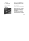
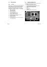
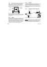
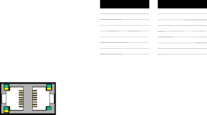
Figure 2-3: Digital input and output connections
Table 2-1: LED control by Rhapsody software
LED 1 green or yellow
LED 2 green or yellow
LED 3 green or yellow
LED 4 green (only!)
DIGITAL I/O
PIN
INPUT
Input 4(p)
Input 1(p)
Input 2(p)
Input 6(p)
Input 3(p)
Return input 6(n)
Input 5(p)
8
7
6
5
4
3
2
1
Return input 1..5(n)
PIN
OUTPUT
Output 4(p)
Return output 4..6(n)
Output 6(p)
Output 2(p)
Output 5(p)
Output 1(p)
Return output 1..3(n)
8
7
6
5
4
3
2
1
Output 3(p)
(p/n see: 2.3.4 How to use the isolated input/output)
Note: The common grounds of the outputs are clustered in
two groups of three outputs. Five input common grounds
are clustered.
LED 1
LED 2
1
In
p
ut
Out
p
ut
1
LED 3
LED 4