


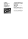
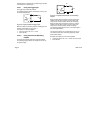
2.3.6 The display connector
The display connector can be used for the connection of a
VGA or a CVBS monitor. Only one of these two
possibilities can be activated at a time. The VGA output
has a resolution of 680x480 pixels in a non-interlaced
mode. The CVBS mode is either CCIR or RS170
compatible depending on the mode set via software. Both
VGA and CVBS outputs support a non-destructive colour
overlay. For connecting a VGA monitor a standard cable
can be used. For the CVBS monitor connection no
standard cable is available. A user made cable must be
connected between the connector pins 9 and 10 where pin
9 is the CVBS connection and pin 10 the ground
connection. A 75 ohm coax cable is preferred.
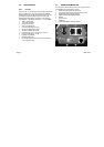
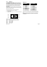
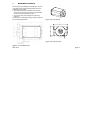
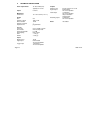
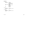
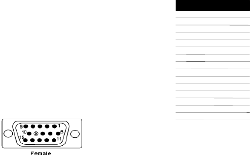
Figure 2-5: DB15 VGA female connector
VGA/CVBS connections
PIN FUNCTION
Monitor ID #2
RED analog video
GREEN analog video
GREEN ground
BLUE analog video
BLUE ground
CVBS analog video
Digital ground
9
8
7
6
5
4
3
2
1
RED ground
SYNC/CVBS ground
Horizontal sync
Vertical sync
Not connected
Monitor ID #0
15
14
13
12
11
10
Monitor ID #1
Figure 2-6: VGA connector pinning
Note 1: The RED, GREEN and BLUE signals are 0.7 Vpp
signals terminated with 75 ohm load. All other signals are
TTL level.
Note 2: Some type of video cards use monitor ID #0..#2 to
determine the type of monitor used. The Inca does not
support automatic monitor detection
Page 10 2005-12-12