


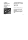
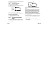
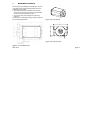
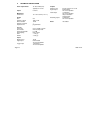

2.3.5 Multi-purpose connector
Looking at the back of the Inca the connector in the left
bottom corner is a multi-purpose connector. The
connector, a 9 pole micro-D connector, contains
connections for an external power supply, 3-wire serial I/O,
the input for an external system reset and a watchdog
function.
5
4
3
2
1
9
8
7
6
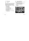
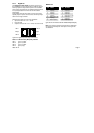
9p-Male
Micro D; MULTI-PURPOSE I/O
PIN
FUNCTION
W-dog alarm-p
Ext. Power
RS232 TxD
Digital ground
RS232 RxD
Ext. Reset-n
Ext. Reset-r
W-dog alarm-n
9
8
7
6
5
4
3
2
1
Ext. Power ground
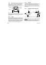
2.3.5.1 Power supply
The Inca is powered by connecting the external power pin
1 to the + pole and pin 6 to the ground of a power supply.
The voltage must be in the range 8..40 volts, but is
typically 12..15 Volt. (The Inca starter kit; PCI 8122 410
56851 or PCMCIA 8122 410 5651 contains a 15 volt 2
Amp. power supply.)
2.3.5.2 RS232
Pin 2 is the RS232 transmit data line.
Pin 3 is the RS232 receive data line.
The RS232 digital ground is connected to pin 7.
Warning:
When using the Micro D to Sub D cable (8122
410 81530) which is also included in the starter kit please
notice that the point 7 and 5 are interchanged all other
points are interconnected one to one.
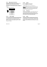
2.3.5.3 Watchdog
The watchdog connection is an opto-isolated output. Pin 4
is the p connection and pin 5 is the n connection. This
output can be switched under software control and can be
made dependent of among others (software) timers. (p/n
see: 2.3.4 How to use the isolated input/output)
2.3.5.4 Reset
A single pole pushbutton connected between the pins 8
and 9 can be used as an external system reset. (Available
in the starterkit). For an internal reset the watchdog output
can be connected directly to the reset input ( pin 4 - pin 8
and pin 5 - pin 9) for this reason the reset input is not Opto
isolated.
2005-12-12 Page 9