


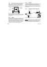

2.3.1 IEEE 1394 (FireWire™)
For the interconnection of the Inca camera to the host PC
a so-called IEEE 1394 interface, also known as
FireWire™, is used. For this link the PC must be equipped
with an IEEE 1394 interface. This IEEE 1394 can be an
onboard OHCI version, a PCILynx- or OHCI- IEEE 1394
PCI expansion board in case of a desktop PC or a
PCMCIA expansion card in case of a notebook. The
number of Inca’s that can be connected to a single IEEE
1394 interface depends on the number of ports available
on the interface. The number of ports can be in the range
one to six but is typically three. The integration of the
physically IEEE 1394 interface into your Windows™
operating system is achieved via a so called device driver.
A device driver for the OHCI and the PCILynx version of
the IEEE 1394 interface will be available for;
Windows NT4, Windows 2000 and Windows XP.
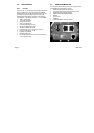
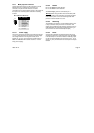
2.3.2 Trigger and Flash
The Inca has an optically isolated trigger input and flash
output.
The trigger input enables the feature to prepare the
capture of an image. If programmed so the capture
process will start immediate when the trigger input is
signaled. A rising or a falling edge on the input can indicate
the trigger.
The flash output can control the external flash unit if
required. The active state (high or low) can be
programmed, see the note for side effect.
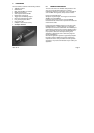
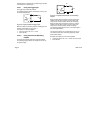
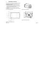
TRIGGER / FLASH
1 234
TRIGGER/FLASH
PIN FUNCTION
Trigger 1(n)
Flash 1(p)
Flash 1(n)
Trigger 1(p)
4
3
2
1
Figure 2-2 Trigger/Flash connector
Note: The start-up sequence for the Inca has
consequences for the flash output. In case the flash output
is configured as a non-inverting output the output is zero
and stays zero and awaits control by the software.
If the output is configured as an inverting output than
during the start-up sequence the output equals the value of
the power supply. This situation stays that way until the
software has taken over the control. In case a flash unit is
2005-12-12 Page 5