


2002 Oct 23 21
Philips Semiconductors Product specification
40 Msps, 10-bit analog-to-digital
interface for CCD cameras
TDA8783
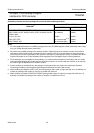
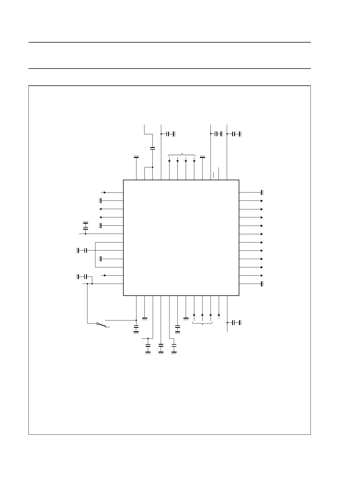
APPLICATION INFORMATION
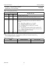
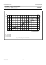
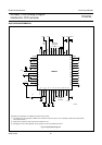
Fig.16 Application diagram.
Depending on the application, the following connections must be made:
(1) The clamp level of the signal input at ADCIN can be tuned from code 00 to code 511 in 0.5 LSB steps of ADC via the serial interface
(clamp ADC activated).
(2) Clamp ADC not activated, direct connection from DACOUT to V
ref
.
(3) All supply pins must be decoupled with 100 nF capacitors as close as possible to the device.
handbook, full pagewidth
MGM504
1
2
3
4
5
6
7
8
9
10
11
36
48 47 46 45 44 43 42 41 40 39 38 37
13 14 15 16 17 18 19 20 21 22 23 24
35
34
33
32
31
30
29
28
27
26
12
25
TDA8783
OGND
D9
D8
D7
D5
D4
D3
D2
D1
D0
DGND1
CLPOB
AGND4
OFDOUT
AMPOUT
AGND1
V
CCA1
CPSDS
AGND5
CLPADC
V
ref
D6
IND
INP
V
CCA3
SHD
SHP
CLPDM
DGND2
V
CCD2
OE
V
CCO
AGND3
CLK
AGCOUT
ADCIN
AGND2
V
CCA2
V
RB
V
RT
DEC1
AGND6
SDATA
SEN
STDBY
V
CCD1
DACOUT
SCLK
from timing
generator
serial
interface
5.0 V 5.0 V
5.0 V
5.0 V
CCD
2.5 to 5.25 V
(3)
1 µF
1 µF
(3)
(3)
(2)
(1)
(3)
5.0 V
(3)
100
nF
1
nF
2.2
nF
1
nF
(3)
220
nF