


Philips Semiconductors
TDA9964
12-bit, 3.0 V, 30 Msps analog-to-digital interface for CCD cameras
Objective specification Rev. 03 — 16 January 2001 4 of 23
9397 750 07918
© Philips Electronics N.V. 2001. All rights reserved.
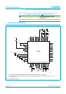
7. Pinning information
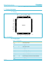
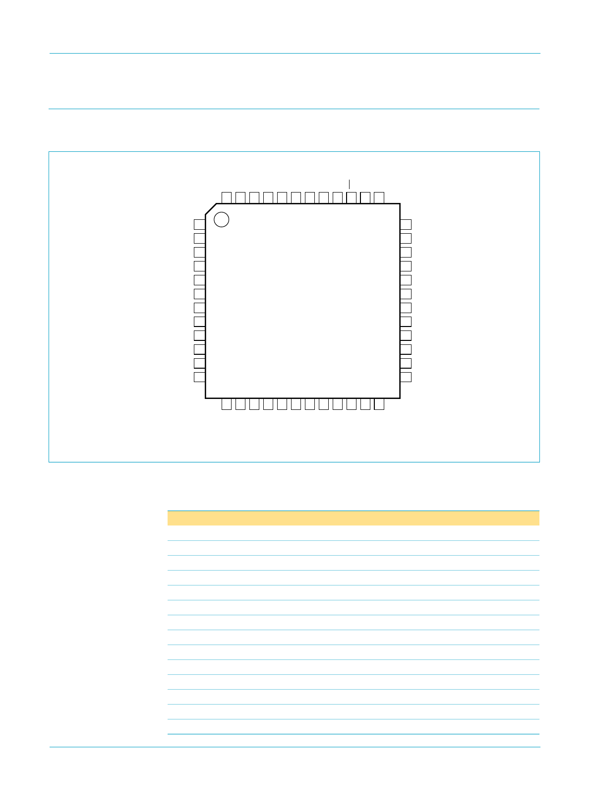
7.1 Pinning
7.2 Pin description
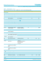
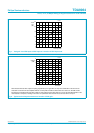
Fig 2. Pin configuration.
1
2
3
4
5
6
7
8
9
10
11
36
35
34
33
32
31
30
29
28
27
26
13
14
15
16
17
18
19
20
21
22
23
48
47
46
45
44
43
42
41
40
39
38
12
24
37
25
TDA9964HL
FCE516
D9
D10
D11
D8
D7
D6
D4
D3
D2
D1
D0
V
CCA1
AGND1
AGND2
IN
AGND3
AGND4
V
CCA2
CPCDS1
CPCDS2
OFDOUT
TEST
D5
CLK
SHD
SHP
CLPOB
BLK
STDBY
AGND6
OGND2
OE
V
CCO2
CLPDM
V
CCA4
DCLPC
OPGAC
OPGA
AGND5
V
CCA3
V
CCD1
V
CCO1
DGND1
SCLK
SEN
OGND1
VSYNC
SDATA
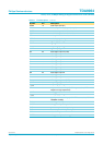
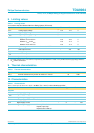
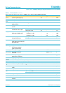
Table 3: Pin description
Symbol Pin Description
V
CCA1
1 analog supply voltage 1
AGND1 2 analog ground 1
AGND2 3 analog ground 2
IN 4 input signal from CCD
AGND3 5 analog ground 3
AGND4 6 analog ground 4
V
CCA2
7 analog supply voltage 2
CPCDS1 8 clamp storage capacitor pin 1
CPCDS2 9 clamp storage capacitor pin 2
DCLPC 10 regulator decoupling pin
OFDOUT 11 analog output of the additional 8-bit control DAC
TEST 12 test mode input pin (should be connected to AGND5)
AGND5 13 analog ground 5
V
CCA3
14 analog supply 3