


6
7
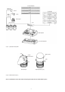
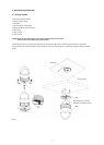
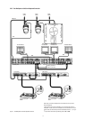
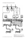
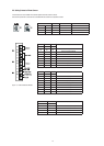
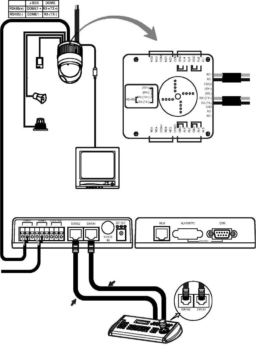
2.2 Basic Conguration of Fastrax II Dome Camera System
Figure 4- Basic installation diagram
The dome camera must be installed by qualied service personnel in accordance with all local and federal electrical and building codes.
The system should be installed according to Figures 4 through 9.
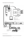
Power
24VAC
STP AWG #24
Sensor
Alarm input
up to 8
Siren
Light
Alarm output
up to 4
BNC
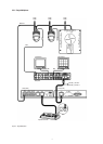
Alarm output
1 ~ 2
Alarm input
1 ~ 4
Power
24VAC
Dome1+
Dome1–
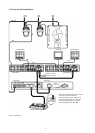
Alarm output
3 ~ 4
Alarm input
5 ~ 8
Monitor
BNC
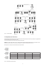
RS-485
Half Duplex mode: RX+, RX–
RS-422
Simplex mode: (RX+), (RX–)
Duplex mode: (TX+), (TX–), (RX+), (RX–)
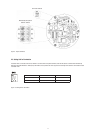
J-Box (Back) J-Box (Front)
unshielded cable
unshielded cable
DATA2 port should be connected
in case that DOME2 port or DVR
port are used.
Up to 128 Dome cameras including
32 alarm mode can be connected
at DOME2 port.
Rear
Keyboard controller