


8
9
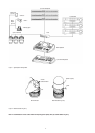
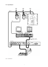
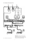
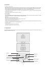
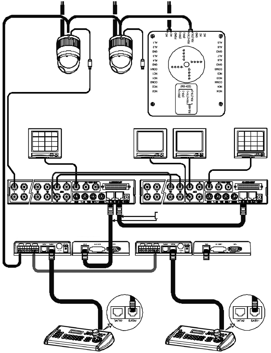
2.2.3 Two Multiplexer with Slave Keyboard Controller
Figure 7 - Two Multiplexer with Slave Keyboard Controller
Rear
Keyboard controller
Master
Power
24VAC
BNC
1st Main Monitor
BNC
BNC
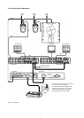
RS-485 (–) Pin No. 4
RS-485 (+) Pin No. 6
J-Box (Back) J-Box (Front)
AWG #24
Power
24VAC
Power
24VAC
Spot Monitor
for Master K/B
1st Multiplexer
BNC
2nd Multiplexer
2nd Main Monitor
Spot Monitor
for Slave K/B
Keyboard controller
Slave
Rear
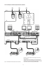
Spot output 1 of the rst multiplexer to be connected to 16
th
input of the
second multiplexer.
n: User, Spot out of n
th
to be connected to (17-n)
th
camera input of the 2
nd
multiplexer. n
th
spot out of the 2
nd
multiplexer to be connected to the n
th
spot
monitor. Each user will see the picture of the selected camera (1 ~ (31-n)) on
n
th
spot monitor of the Mux 2 by selecting camera No. + Cam.