


English
OSD (On Screen Display) Controls
26
En
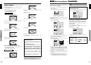
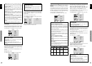
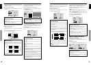
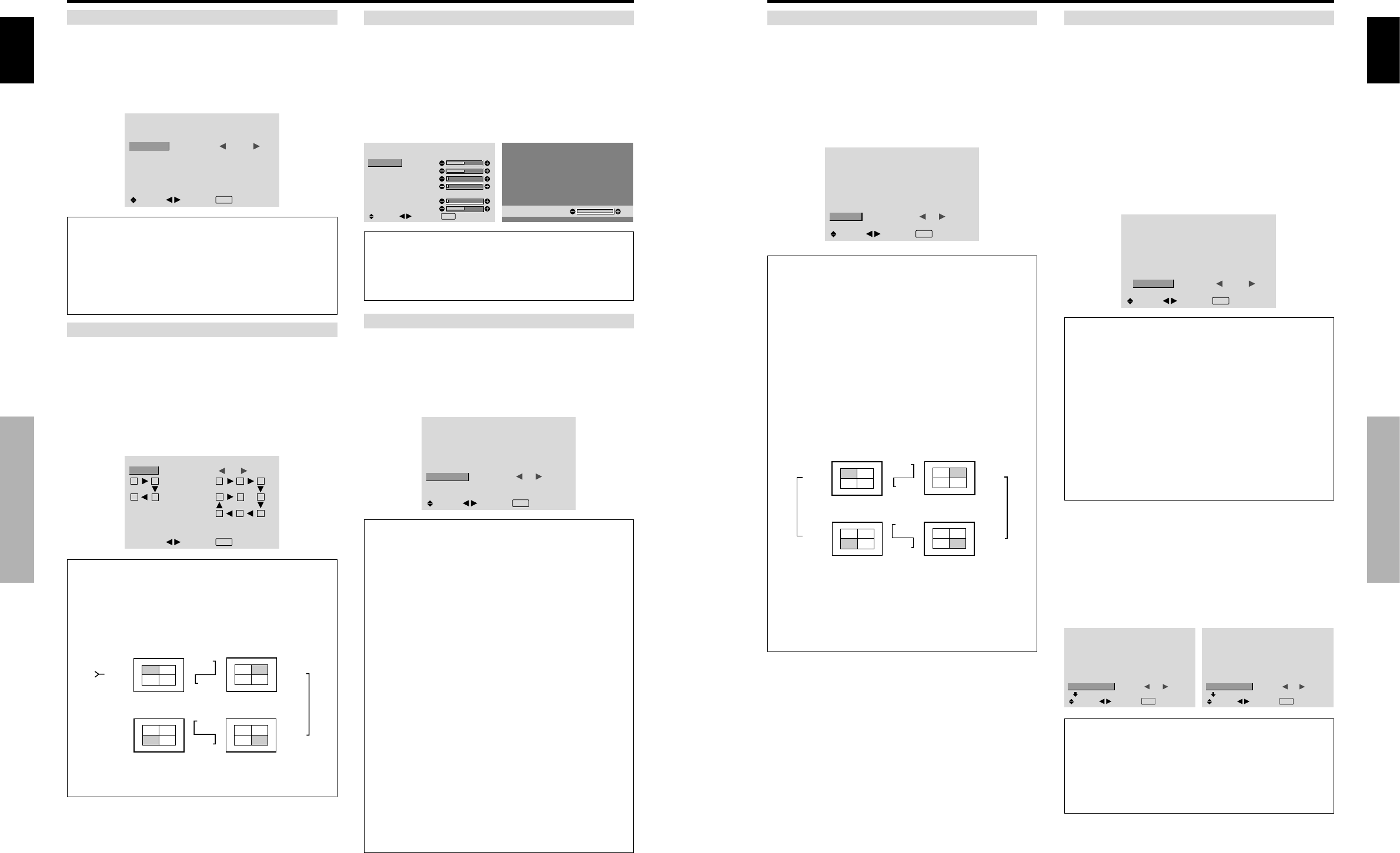
AUTO ID
This feature automatically sets the ID numbers of multiple
displays connected to each other.
Example: Setting “ON”
Set the ID number for the No. 1 display on ID NUMBER
menu.
On “AUTO ID” of “VIDEO WALL” menu, select “ON”,
then press the MENU/SET button.
AUTO ID
: ON
1
2
4
3
1
2
8
9
3
4
6
5
7
WIRED CABLE
CONNECTION TURN
ADJ.
EXIT
RETURN
AUTO ID
Information
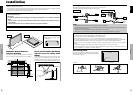
Ⅵ AUTO ID settings
ON: Enables Auto ID function. In the case shown below,
display 1 will be set as ID 1, display 2 as ID2, etc.
This can be set only when a 2×2 or 3×3 video wall is
selected.
REMOTE
IN
REMOTE
IN
REMOTE
OUT
REMOTE
OUT
REMOTE
IN
REMOTE
OUT
REMOTE
OUT
REMOTE
IN
No.1
No.2
No.3No.4
No.1
No.2
No.3No.4
No.1
No.2
No.3No.4
No.1
No.2
No.3No.4
Display 1
Display 2
Display 4
Display 3
OFF: Disables Auto ID function.
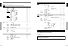
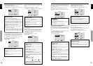
DISP. MODE
Select the screen mode from between two options
(NORMAL, ADJUST).
Example: Setting “ADJUST”
On “DISP. MODE” of “VIDEO WALL” menu, select
“ADJUST”.
VIDEO WALL
DIVIDER
POSITION
DISP. MODE
AUTO ID
SCREEN
P. ON DELAY
ABL LINK
REPEAT TIMER
: 1
: ADJUST
: OFF
: OFF
: OFF
: OFF
SEL.
ADJ.
EXIT
RETURN
Information
Ⅵ DISP. MODE settings
NORMAL: Combines enlarged screens and creates
multiple screens.
ADJUST: Corrects misalignment of combined screen
portions and creates multiple screens
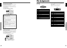
SCREEN
The position of the image can be adjusted and flickering
of the image can be corrected.
Example: Adjusting the vertical position
On “VIDEO WALL” menu, select “SCREEN”, then press
the MENU/SET button.
The “SCREEN” screen appears.
On “V.POSITION” of “SCREEN” menu, adjust the position.
SCREEN
SCREEN SIZE
V.POSITION
H.POSITION
V.SIZE
H.SIZE
AUTO PICTURE
PHASE
CLOCK
: 4
:
3
: OFF
SEL.
ADJ.
EXIT RETURN
V.POSITION
+64
Information
Ⅵ SCREEN settings
These are the same functions as the SCREEN menu on
page 16.
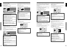
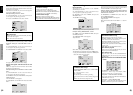
P. ON DELAY (Power on delay)
Use this function to activate power-on delay.
Turn on the AUTO ID before the following operations.
Example: Setting “ON”
On “P. ON DELAY” of “VIDEO WALL” menu, select
“ON”.
VIDEO WALL
DIVIDER
POSITION
DISP. MODE
AUTO ID
SCREEN
P. ON DELAY
ABL LINK
REPEAT TIMER
: 1
: NORMAL
: OFF
: ON
: OFF
: OFF
SEL.
ADJ.
EXIT
RETURN
Information
Ⅵ P. ON DELAY settings
ON: Turns on the main power of each display after a
delay time.
OFF: Turns on the main power of all displays at the
same time.
(Only for 16 and 25 screens)
MODE1: Turns on the main power of each display
delayed.
MODE2: Turns on the main power of each display more
delayed.
* Once this function has been set to “ON”, the POWER
ON/OFF button on the remote control does not function
except for the No.1 monitor.
By pressing the POWER ON button on the remote
control the No.1 monitor will turn on and the others
will be turned on one by one automatically.
* From the second monitor onward, neither the POWER
button on the unit nor the POWER ON button on the
remote control works. However, by pressing and holding
the POWER ON button for more than 3 seconds, the
monitor will be turned on.
English
OSD (On Screen Display) Controls
27
En
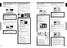
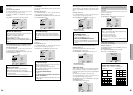
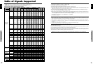
ABL LINK
Use this function to set a uniform brightness for each
display.
Turn on the AUTO ID and set the DIVIDER (at 1, 4 or 9)
before the following operations.
Example: Setting “ON”
On “ABL LINK” of “VIDEO WALL” menu, select “ON”,
then press the MENU/SET button.
VIDEO WALL
DIVIDER
POSITION
DISP. MODE
AUTO ID
SCREEN
P. ON DELAY
ABL LINK
REPEAT TIMER
: 1
: NORMAL
: OFF
: OFF
: ON
: OFF
SEL.
ADJ.
EXIT
RETURN
Information
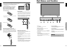
Ⅵ ABL LINK settings
ON: Sets a uniform brightness for each screen in a video
wall. This can be set only when a 2×2 or 3×3 video
wall is selected.
OFF: Sets the individual screen brightness for each
screen in a video wall.
* When this function is set “ON”, connect your plasma
displays with the remote cable (optional) in the order of
the position numbers for the 2×2 video wall. See the
drawing below.
* If there are changes in the DIVIDER or POSITION,
the ABL LINK will automatically turn OFF.
REMOTE
IN
REMOTE
IN
REMOTE
OUT
REMOTE
OUT
REMOTE
IN
REMOTE
OUT
REMOTE
OUT
REMOTE
IN
No.1
No.2
No.3No.4
No.1
No.2
No.3No.4
No.1
No.2
No.3No.4
No.1
No.2
No.3No.4
Display 1
Display 2
Display 4
Display 3
* With the 3×3 video wall, connect the final display to
the first display the same way as with 2×2 video wall.
Note:
The remote control can be operated unless the
IR REMOTE is set to “OFF”.
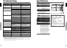
REPEAT TIMER
Use this to set two timers. Each timer can use the
DIVIDER, SOURCE and WORK TIME functions.
Turn on the AUTO ID and set the DIVIDER (at 1, 4 or 9)
before the following operations.
Example:
TIMER1...VIDEO1 will be displayed for 3 minutes.
TIMER2...PC1 will be displayed for 6 minutes in a
2×2 video wall.
On “REPEAT TIMER” of “VIDEO WALL” menu, select
“ON”, then press the MENU/SET button.
The “REPEAT TIMER” screen appears.
Adjust the items.
REPEAT TIMER
: 1
: VIDEO1
: 00H03M
: 4
: PC1DSUB
: 00H06M
SEL.
ADJ.
EXIT
RETOUR
1 DIVIDER
SOURCE
WORK TIME
2 DIVIDER
SOURCE
WORK TIME
Information
Ⅵ REPEAT TIMER settings
DIVIDER: Divide the screen into 1, 4 or 9 sections.
SOURCE: Set the input mode to be displayed.
WORK TIME: Can be set to up to 4 hours 15 minutes
in units of 1 minute.
If you set both timers, Timer 1 and Timer 2 run
consecutively.
In the case of the Video wall, timer No.1 can be used to
control all the displays simultaneously.
* This becomes effective when the on-screen menu goes
out.
Advanced OSD Settings Menu
Setting the menu mode
This allows you to access full menu items.
When P. ON DELAY or ABL LINK is ON, this won’t be
turned OFF.
Example: Setting “ON”
On “ADVANCED OSD” of “MAIN MENU”, select “ON”.
MAIN MENU
1 / 2
:
OFF
SEL.
ADJ.
EXIT
EXIT
PICTURE
SOUND
SCREEN
OPTION1
ADVANCED OSD
NEXT PAGE
MAIN MENU
1 / 2
:
ON
SEL.
ADJ.
EXIT
EXIT
PICTURE
SOUND
SCREEN
OPTION1
OPTION2
OPTION3
ADVANCED OSD
NEXT PAGE
Information
Ⅵ ADVANCED OSD settings
ON: All of the main menu items are available for
advanced users.
OFF: Some of the main menu items are not available
(e.g. OPTION2 and OPTION3).