English
Part Names and Function
6
En
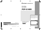
A AC IN
Connect the included power cord here.
B EXT SPEAKER L and R
Connect speakers (optional) here. Maintain the correct
polarity. Connect the
(positive) speaker wire to the
EXT SPEAKER terminal and the (negative)
speaker wire to the
EXT SPEAKER terminal on
both LEFT and RIGHT channels.
Please refer to your speaker’s owner’s manual.
C VIDEO1, 2, 3 (BNC, RCA, S-Video)
Connect VCR’s, DVD’s or Video Cameras, etc. here.
VIDEO1 can be used for Input or Output (see page
24).
D AUDIO1, AUDIO2, AUDIO3
These are audio input terminals.
The input is selectable. Set which video image to allot
them from the SOUND menu screen.
E COMPONENT1
Connect DVD’s, High Definition or Laser Discs, etc.
here.
F PC2/COMPONENT2
PC2: You can connect an analog RGB signal
and the syncronization signal.
COMPONENT2
: You can connect DVDs, High
Definition sources, Laser Discs, etc.
here.
This input can be set for use with an
RGB or component source (see page
17).
G PC1 (mini D-Sub 15pin)
Connect an analog RGB signal from a computer, etc.
here. This input can be used for Input or Output (see
page 24).
H PC3
(DVI 24pin)
Connect a digital signal (TMDS) from a source with a
DVI output.
I RS-232C
Never connect any component to this connector
without first consulting your Pioneer installation
technician.
This connector is used for plasma display setup
adjustments.
J REMOTE IN
Connect the remote cable* to the remote control’s
remote jack to obtain wired remote control.
K REMOTE OUT
Connect the remote cable* to the REMOTE IN jack of
the other display monitor to obtain wired remote
control.
* The 1/8 Stereo Mini cable must be purchased separately.
Rear View/ Terminal Board
English
Part Names and Function
7
En
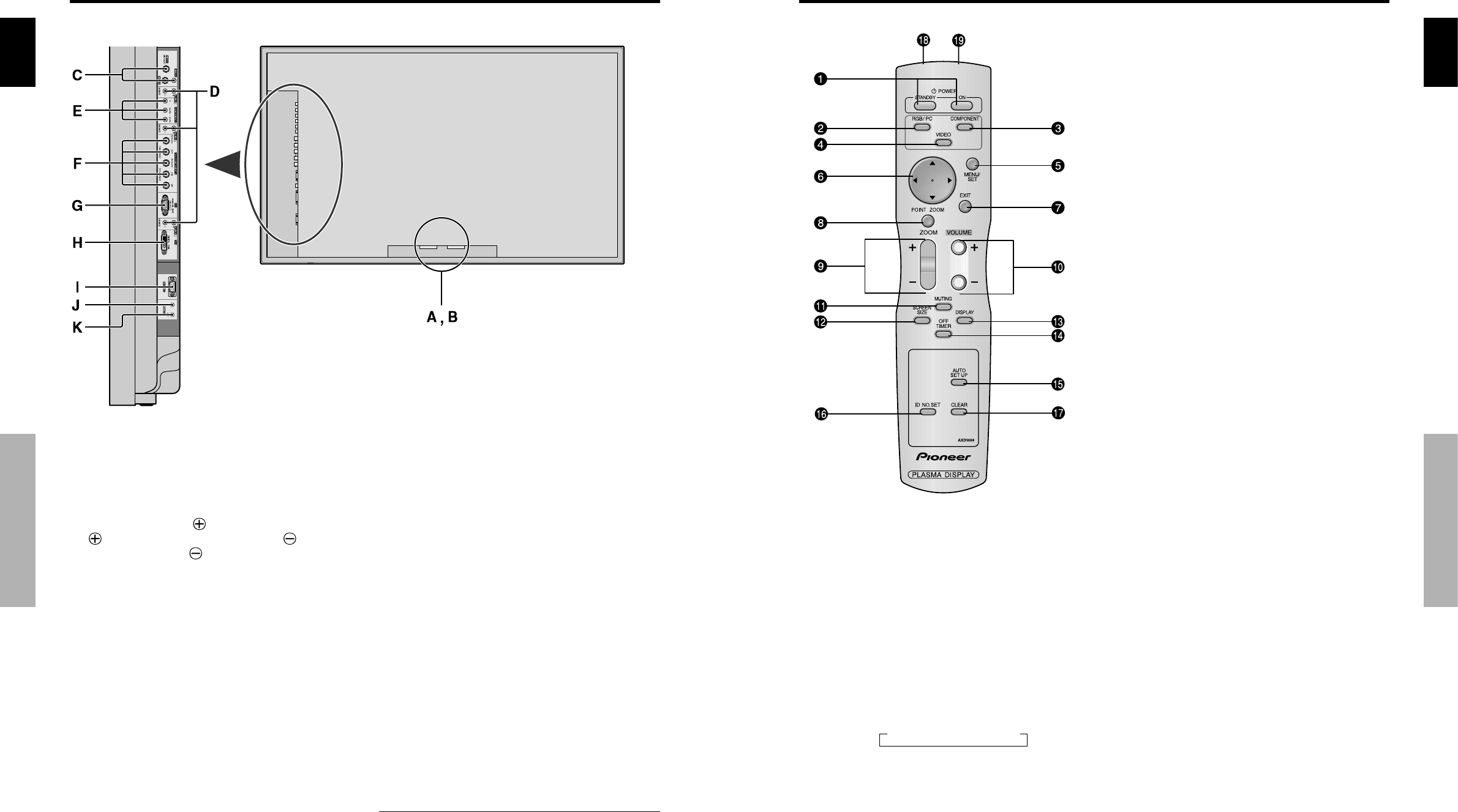
q POWER ON/STANDBY
Switches the power on/standby.
(This does not operate when STANDBY/ON indicator
of the main unit is off.)
w RGB/PC
Press this button to select RGB/PC as the source.
RGB/PC can also be selected using the INPUT/EXIT
button on the monitor.
e COMPONENT
Press this button to select COMPONENT as the source.
COMPONENT can also be selected using the INPUT/
EXIT button on the monitor.
r VIDEO
Press this button to select VIDEO as the source.
VIDEO can also be selected using the INPUT/EXIT
button on the monitor.
t MENU/SET
Press this button to access the OSD controls.
Press this button during the display of the main menu
to go to the sub menu.
y CURSOR (▲ / ▼ /
ᮤ
/
ᮣ
)
Use these buttons to select items or settings and to
adjust settings.
u EXIT
Press this button to exit the OSD controls in the main
menu. Press this button during the display of the sub
menu to return to the previous menu.
i POINT ZOOM
Press this button to display the pointer.
o ZOOM (+ /–)
Enlarges or reduces the image.
!0 VOLUME (+ /–)
Adjusts the sound volume.
!1 MUTING
Mutes the sound.
!2 SCREEN SIZE
Automatically detects the signal and sets the aspect ratio.
SCREEN SIZE button is not active for all signals.
!3 DISPLAY
Displays the source settings on the screen.
!4 OFF TIMER
Activates the off timer for the unit.
!5 AUTO SET UP
Press this button to adjust PHASE, CLOCK, Position,
and Contrast automatically, or to switch the screen size
to ZOOM mode automatically with the superimposed
caption displayed fully only when the picture contains
dark areas above and below the picture.
!6 ID NO. SET
Set the ID number in the remote control. The remote
control can then be used only for a display with the
same ID number. When several displays are used
together they can be controlled individually.
!7 CLEAR
Clears the number set by the ID NO. SET button.
!8 Remote control signal transmitter
Transmits the remote control signals.
!9 Remote Jack
Insert the plug of the remote cable (The 1/8 Stereo
Mini cable) here when using the supplied remote
control in the wired condition.
Remote Control
A VIDEO1 A VIDEO2 A VIDEO3