


14
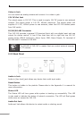
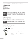
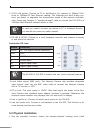
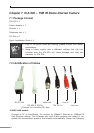
1.RJ-45LANsocket:ConnecttoPCorHub/Switch.Forconnectto10Base-TEth-
ernetor100Base-TXFastEthernetcabling.ThisEthernetportbuiltN-Waypro-
tocol can detect or negotiate the transmission speed of the network automati-
cally.PleaseuseCategory5“straightthrough”cabletoconnecttheICA-525toa
100MbpsFastEthernetnetworkswitchorhub.
Note
IncaseyouneedtoconnectthedevicetoPCornotebookdirectly,
youshouldusecrossovercableinstead.
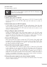
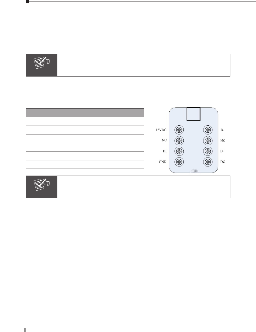
2.RS-485&DI/DO:Connecttoalocalkeyboardcontrollerandconnecttosensor
in and alarm out devices
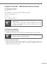
Inside the TEL box:
Name Function
12VDC DC 12V output (50mA maximum)
GND GND
D+ RS485 data +
D- RS485 data -
DI Digital signal input
DO Digital signal output
Note
The RS-485 of ICA-525 is master that can control external scanner.
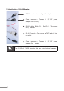
3. Local Video output (BNC port): The Network Camera also provides composite
video output. User can use BNC video cable to connect the Network Camera
with a TV monitor or VCR.
4. DC-in Jack: The input power is 12VDC. Note that supply the power to the Net
-
work Camera with standard power adapter included in package. Otherwise, the
improper power adapter may damage the unit and result in danger.
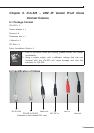
5. Line in (audio in): Connect an audio input source to the ICA-525.
6. Line out (audio out): Connect a loud speaker to the ICA-525. This function is for
voice alerting and two-way audio.
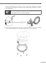
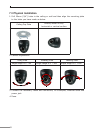
6.3 Physical Installation
1. Use the provided L-wrench, loosen the tamper-resistant housing cover (with