SPEED DOME CAMERA User Guide
18
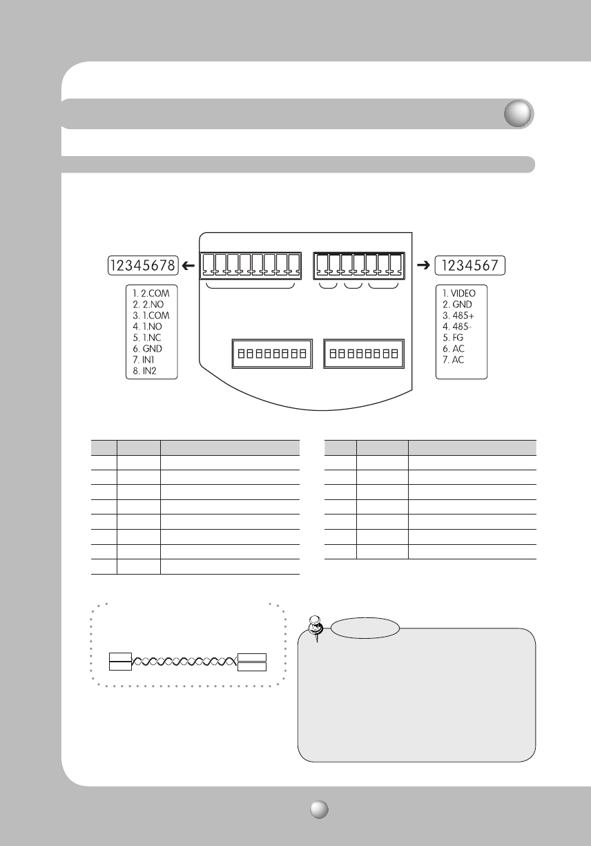
For the camera wiring, please refer to the picture below.
The camera's wiring interface board is fitted to the housing, this is sold separately.
(When using coaxial communication, a separate control signal connection is not required.)
• The maximum power capacity of the built-
in relay is 30V DC/2A, 125V AC/0.5A, and
250V AC/0.25A.
• Connecting the power connector and GND
incorrectly to the NC/NO and COM ports
may cause a short circuit and fire,
damaging the camera.
Notes
Camera Wiring Interface Board
· RS485 Communications
Camera
485+
485-
R+/RX+
R-/RX-
Controller
or DVR
Control Signal Connection
Power, Video & Communication Signal Connection
* The provided BNC cable’s blue line is Video
Output, while the black line is the Ground.
* Power supply adaptor (AC) has no polarities.
Controller & Auxiliary Signal Connection
Alarm Video Controller Power Supply
No. Name Usage
1 VIDEO Video Output
2 GND Ground
3 485+
Controller Data Line
4 485-
Controller Data Line
5
FG Field Ground
6
AC AC 24V
7
AC AC 24V
No. Name Usage
1 2.COM Alarm Output 2 (Common)
2 2.NO Alarm Output 2 (Normal Open)
3 1.COM
Alarm Output 1 (Common)
4 1.NO
Alarm Output 1 (Normal Open)
5 1.NC Alarm Output 1 (Normal Close)
6 GND Ground
7 IN1 Alarm Input Sensor Terminal 1
8 IN2 Alarm Input Sensor Terminal 2
Component Names and Functions


