


0
1
2
1
23
SCAN
OUT
SCAN
IN
SHUTTER 1st
BARRIER
SHUTTER 2nd
CARD LID
CAMERA
MODE
PLAY
SET
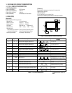
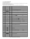
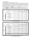
Table 4-2. Key Operation
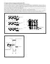
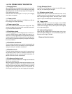
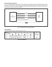
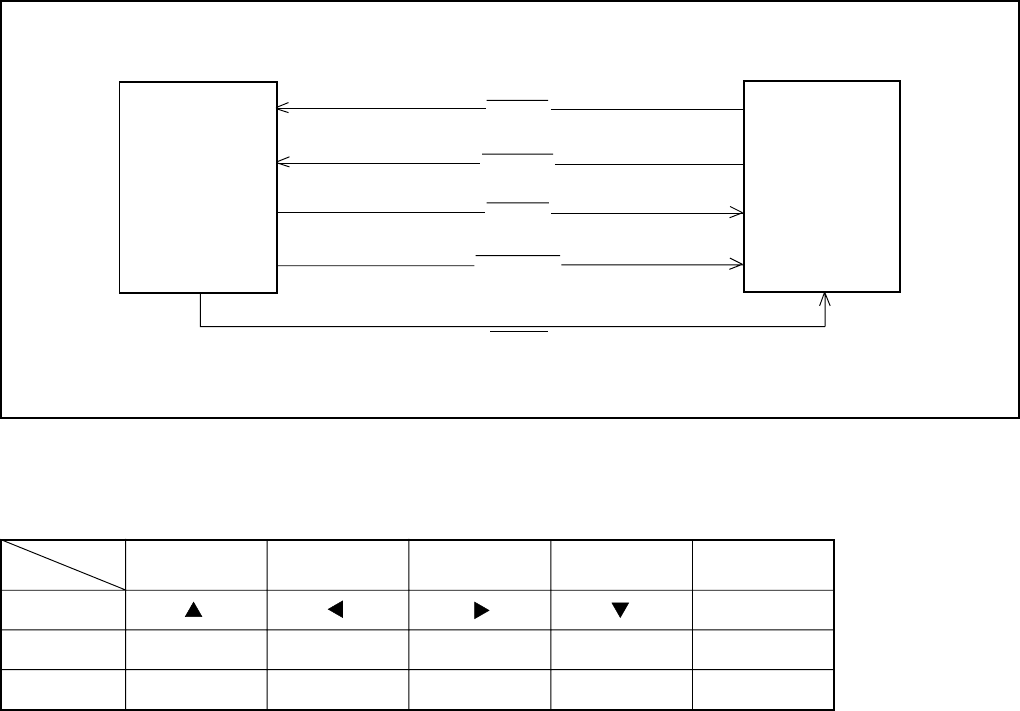
2. Internal Communication Bus
The SY1 circuit board carries out overall control of camera operation by detecting the input from the keyboard and the condition
of the camera circuits. The 8-bit microprocessor reads the signals from each sensor element as input data and outputs this data
to the camera circuits (ASIC) or to the LCD display device as operation mode setting data. Fig. 4-1 shows the internal commu-
nication between the 8-bit microprocessor and ASIC.
3. Key Operaiton
For details of the key operation, refer to the instruction manual.
8-bit
microprocessor
ASIC
32 bit
CPU
S. REQ
RESET
ASIC SO
ASIC SI
ASIC SCK
Fig. 4-1 Internal Bus Communication System
4
MACRO
-
TEST