


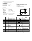

1-2. CA2 CIRCUIT DESCRIPTION
1. Circuit Description
1-1. Scannning converter (Interlace converter)
This circuit uses the function of a 64-Mbit SDRAMs to con-
vert the non-interlaced signal which is output from the CCD
into an interlaced signal for the video monitor.
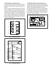
1-2. Camera signal processor
This comprises circuits such as the digial clamp circuit, white
balance circuit, circuit, color signal generation circuit, ma-
trix circuit and horizontal aperture circuit.
1. Digital clamp circuit
The optical black section of the CCD extracts 16-pixel aver-
aged values from the subsequent data to make the black level
of the CCD output data uniform for each line. The 16-pixel
averaged value for each line is taken as the sum of the value
for the previous line multiplied by the coefficient k and the
value for the current line multiplied by the coefficient 1-k.
2. White balance circuit
This circuit controls the white balance by using the AWB judge-
ment value computed by the CPU to control the gain for each
R, G and B pixel based on the CCD data which has been
read.
3. circuit
This circuit performs (gamma) correction in order to maintain
a linear relationship between the light input to the camera
and the light output from the picture screen.
4. Color generation circuit
This circuit converts the CCD data into RGB signals.
5. Matrix circuit
This circuit generates the Y signals, R-Y signals and B-Y sig-
nals from the RGB signals.
6. Horizontal aperture circuit
This circuit is used generate the aperture signal.
1-3. SDRAM controller
This circuit outputs address, RAS, CAS and AS data for con-
trolling the SDRAM. It also refreshes the SDRAM.
1-4. PIO
The expansion parallel port can be used for functions such
as stroboscope control and LCD driver control.
1-5. SIO (Serial control)
This is the interface for the 8-bit microprocessor.
1-6. TG, SG block
This is the timing generation circuit which generates the clocks
(vertical transfer clock and electronic shutter clock) which drive
the CCD.
1-7. 8-bit D/A circuit (Audio)
This circuit converts the audio signals (analog signals) from
the microphone to 8-bit digital signals.
1-8. 8-bit A/D circuit (Audio)
The audio signals which were converted to digial form by the
8-bit A/D circuit are temporarily to a sound buffer and then
recorded in the SSFDC card. During playback, the 8-bit D/A
circuit converts these signals into analog audio signals.
1-9. Sound buffer
Audio memory
1-10. LCD driver
The Y/C signals which are input to the LCD driver are con-
verted to RGB signals, and the timing signal which is neces-
sary for LCD monitor display and the RGB signals are then
supplied to the LCD monitor.
1-11. LCD monitor
This is the image display device which displays the image
signals supplied from the LCD driver.
1-12. UART
This circuit is used for transmitting serial data to a PC. The
interface is RS-232C-compatible.
1-13. SSFDC control
This reads data from the SSFDC card and stores it in SDRAM,
and writes out the image data stored in SDRAM. In addition,
error correction is carried out when the data is read.
1-14. MJPEG compression
Still and continuous frame data is converted to JPEG format,
and movie images are compressed and expanded in MJPEG
format.
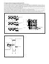
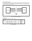
2. Outline of Operation
When the shutter opens, the reset signals, TEST0, TEST1
and the serial signals (“take a picture” commands) from the
8-bit microprocessor are input and record operation starts.
When the TG drives the CCD, picture data passes through
the A/D and is then input to the ASIC as 10-bit data. This data
then passes through the DCLP, AWB, shutter and circuit,
after which it is input to the SDRAM. The AWB, shutter,
and AGC value are computed from this data, and two expo-
sures are made to obtain the optimum picture. The data which
has already been stored in the SDRAM is read by the CPU
and color generation is carried out. Each pixel is interpolated
from the surrounding data as being either R, G or B primary
color data to produce R, G and B data. At this time, correction
of the lens distortion which is a characteristic of wide-angle
lenses is carried out. Aperture correction is carried out, and
in case of still picture the data is then compressed by the
JPEG method and in case of picture it is compressed by
MJPEG method and is written to SSFDC card. When the data
is to be output to an external device, it is read JPEG picture
data from the SSFCD card and output to PC via the UART.