


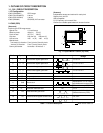
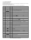

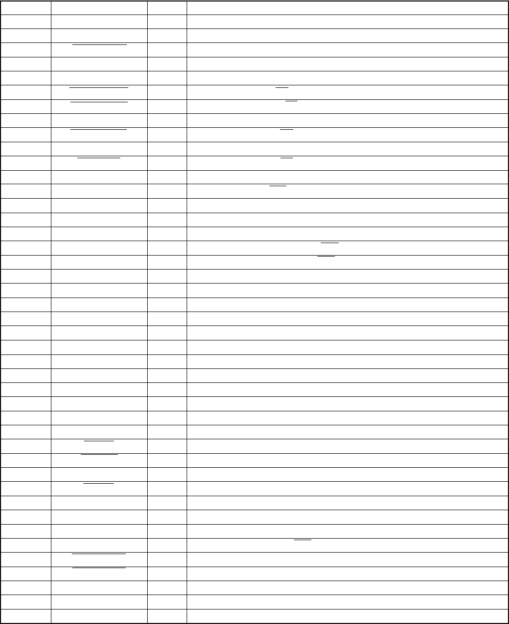
Pin Signal
1
3~7
8
9
10
11
13
14~19
20
21
22
31
32~69
70
71
73
74
75
76
77
78
79
80
81
82
84
86
87
88~90
83
85
91~93
CHG VOL
SCAN IN 0~4
AVREF
STBY (R) LED
STBY (G) LED
VSS
NOT USED
AVREF ON
NOT USED
CHG ON
NOT USED
VSS
NOT USED
P (A) ON
P ON
DIN CONNECT
NOT USED
AV JACK
SO
SCK
IC
XOUT
XIN
VDD
XCIN
XCOUT
RESET
BAT OFF
RXD
S. REQ
NOT USED
SCAN OUT 0~2
I/O
I
I
I
O
O
-
O
-
O
-
O
-
-
-
O
O
I
-
I
I
O
O
-
O
I
-
I
O
I
I
I
I
-
O
Outline
Strobe charge voltage input (analog input)
Key matrix input
A/D converter standard voltage input terminal
Standby LED (red) ON/OFF signal L : LED light
Standby LED (green) ON/OFF signal L : LED light
GND
Self-timer LED (red) ON/OFF signal L : LED light
-
A/D standard power ON/OFF signal L : ON
-
Flash charge ON/OFF signal H : ON
-
GND
-
DC/DC converter (analog) ON/OFF signal H : ON
DC/DC converter (digital) ON/OFF signal H : ON
DIN jack connect detection signal L : Connection
-
AV output cable connection detection signal L : Connection
Serial communication data input (←ASIC)
Serial communication data output (→ASIC)
Serial communication clock output (→ASIC)
Connect to Vss
Main clock oscillation terminal (4 MHz)
Main clock oscillation terminal
Power supply terminal
Sub clock oscillation terminal (32.768 kHz)
Sub clock oscillation terminal
Reset input
Battery OFF detection signal L : OFF
RS-232C RXD input terminal
Serial communication request signal L : Request
-
Key matrix output
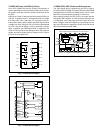
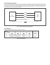
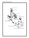
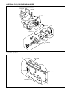
1-5. SY1 CIRCUIT DESCRIPTION
1. Configuration and Functions
For the overall configuration of the SY1 circuit board, refer to the block diagram. The configuration of the SY1 circuit board
centers around a 8-bit microprocessor (IC301).
The 8-bit microprocessor handles the following functions.
1. Operation key input, 2. Mode LCD display, 3. Clock control, 4. Power ON/OFF, 5. Storobe charge control
SI
72
23~30
12
SELF LED (R)
95
96
97
98
99
100
LCD ON
ASIC TEST 0
ASIC RESET
AVSS
BATTERY
O
O
O
O
-
I
LCD monitor power ON/OFF signal H : ON
ASIC reset signal L : Reset output
ASIC reset control signal
A/D converter GND power terminal
Battery voltage input (analog input)
ASIC reset control signal
ASIC TEST 1
94
NOT USED
-
-
Table 4-1. 8-bit Microprocessor Port Specification
AVDD
-
A/D converter analog power terminal
2
NOT USED
-
-