


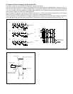
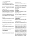
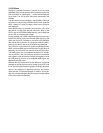
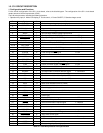

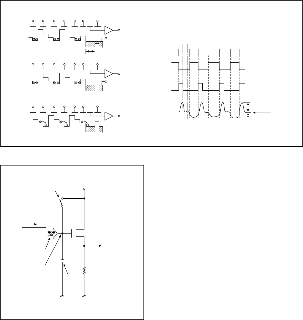
Fig. 1-5. Horizontal Transfer of CCD Imager and Extraction of Signal Voltage
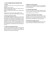
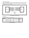
Fig. 1-6. Theory of Signal Extraction Operation
H1 H2 H1 H2 H1 HOG RG
CCD OUT
PD
Floating diffusion
(1)
H1 H2 H1 H2 H1 HOG RG
CCD OUT
PD
(2)
H1 H2 H1 H2 H1 HOG RG
CCD OUT
(3)
H1
H2
RG
CCD OUT
3.5V
0V
3.5V
0V
13.5V
0V
Black level
RG pulse peak signal
Signal voltage
(1) (2) (3)
Reset gate pulse
12V Pre-charge drain bias PD
Direction of transfer
Voltage output
Electric
charge
H Register
Floating diffusion gate is
floated at a high impedance.
C is charged
equivalently
5. Transfer of Electric Charge by the Horizontal CCD
The transfer system for the horizontal CCD emplays a 2-phase drive method.
The electric charges sent to the final stage of the horizontal CCD are transferred to the floating diffusion, as shown in Fig. 1-5.
RG is turned on by the timing in (1), and the floating diffusion is charged to the potential of PD. The RG is turned off by the timing
in (2). In this condition, the floating diffusion is floated at high impedance. The H1 potential becomes shallow by the timing in (3),
and the electric charge now moves to the floating diffusion.
Here, the electric charges are converted into voltages at the rate of V = Q/C by the equivalent capacitance C of the floating
diffusion. RG is then turned on again by the timing in (1) when the H1 potential becomes deep.
Thus, the potential of the floating diffusion changes in proportion to the quantity of transferred electric charge, and becomes
CCD output after being received by the source follower. The equivalent circuit for the output circuit is shown in Fig. 1-6.
RG pulse leak signal