


6
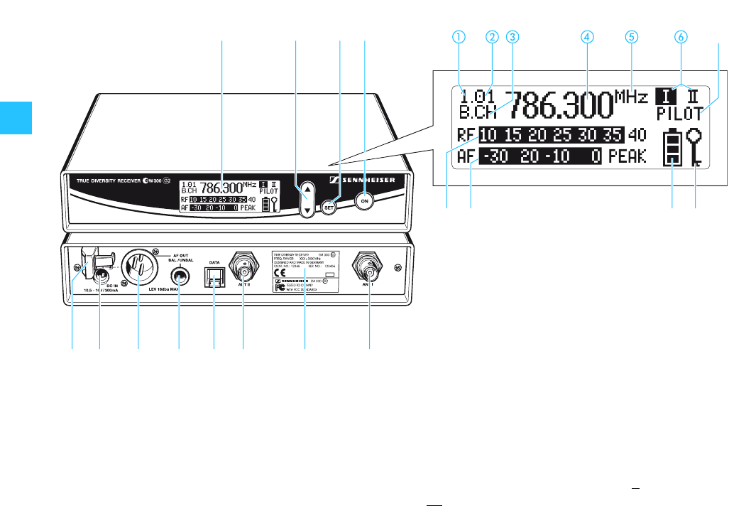
Overview of operating controls
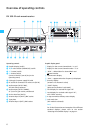
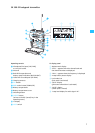
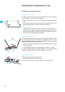
EM 300 G2 rack-mount receiver
³·» ¿
´ ² ¶ º ¾ µ ¸ ¹
ቭቫቪቩ
ቨ
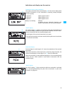
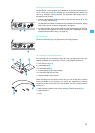
Operating controls Graphic display panel
³ Graphic display, backlit
· ̄/̆ rocker button (DOWN/UP), backlit
» SET button, backlit
¿ ON button, backlit
(serves as the ESC (cancel) key in the
operating menu)
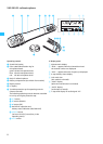
´ Cable grip for power supply DC cable
² DC socket for connection of mains unit (DC IN)
¶ Audio output (AF OUT BAL),
XLR-3M socket, balanced
º Audio output (AF OUT UNBAL),
¼” (6.3 mm) jack socket, unbalanced
¾ Service interface (DATA)
µ Antenna input II (ANT II), BNC socket
¸ Type plate
¹ Antenna input I (ANT I), BNC socket
ቢ Display for the current channel bank “1...8, U”
ባ Display for the current channel number “1...8”
ቤ “B.CH“ – abbreviation for channel B
ank and
CH
annel number
ብ Alphanumeric display
ቦ “MHz“ – appears when the frequency is displayed
ቧ Diversity display
(antenna I or antenna II active)
ቨ “PILOT” display
(pilot tone evaluation is activated)
ቩ Level display for received RF signal “RF”
ቪ Level display for received audio signal “AF”,
with “PEAK“ warning
ቫ 4-step transmitter battery status display
ቭ Lock mode icon
(lock mode is activated)
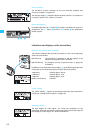
Note:
For further illustrations and examples of the different
standard displays, please refer to the section
“Selecting the standard display” on page 32.