Chapter 1 Overview
24 Chapter 1 Overview
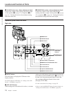
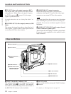
Rear and Bottom
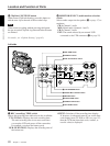
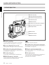
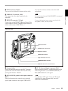
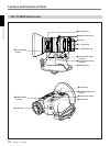
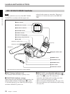
1 TALLY (back tally) indicator (red)
This indicator lights during recording. It will not light
if the TALLY switch 2 is set to OFF. This indicator
also blinks to indicate warnings in the same manner as
the REC/TALLY indicator in the viewfinder.
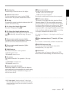
6 WRR connector
7 DC OUT connector
8 VTR connector
9 BREAKER button
Location and Function of Parts
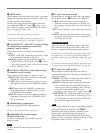
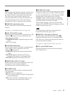
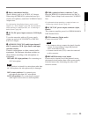
4 TC OUT (time code output) connector (BNC)
This outputs time code signals from the built-in time
code generator. When a time code signal is input to
the TC IN connector (3 on page 23), this output
signal is synchronized to it.
For details about time code, see “Setting Time Values” on
page 59.
5 S VIDEO OUT (S-video output) connector (DIN
4-pin)
This outputs the image being shot or played back as S-
video signals. Connect to the S-video input connector
on an external VCR or video monitor.
6 MONITOR OUT (output) connector
Outputs the image being shot or played back as
composite video signals. Connect to the video input
connector on an external VCR or video monitor.
Note
The output signal from this connector may discontinue
when switching the operation between recording and
playback. Do not use as a reference signal for external
equipment.
7 AUDIO OUT CH-1/CH-2 (audio output channel
1 and 2) connectors (phono jacks)
These output the sound being recorded or played back.
Connect to a stereo amplifier or video monitor’s audio
input connectors.
2 TALLY switch
Set this switch to ON to activate the TALLY indicator
1 function.
For details, see “Warning System” on page 115.
1 TALLY indicator
2 TALLY switch
3 Battery attachment
interface
4 DC IN connector
5 AUDIO IN CH-1/CH-2
connectors and input
selection switches


