


Chapter 1 Overview
28 Chapter 1 Overview
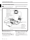
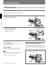
Location and Function of Parts
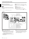
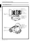
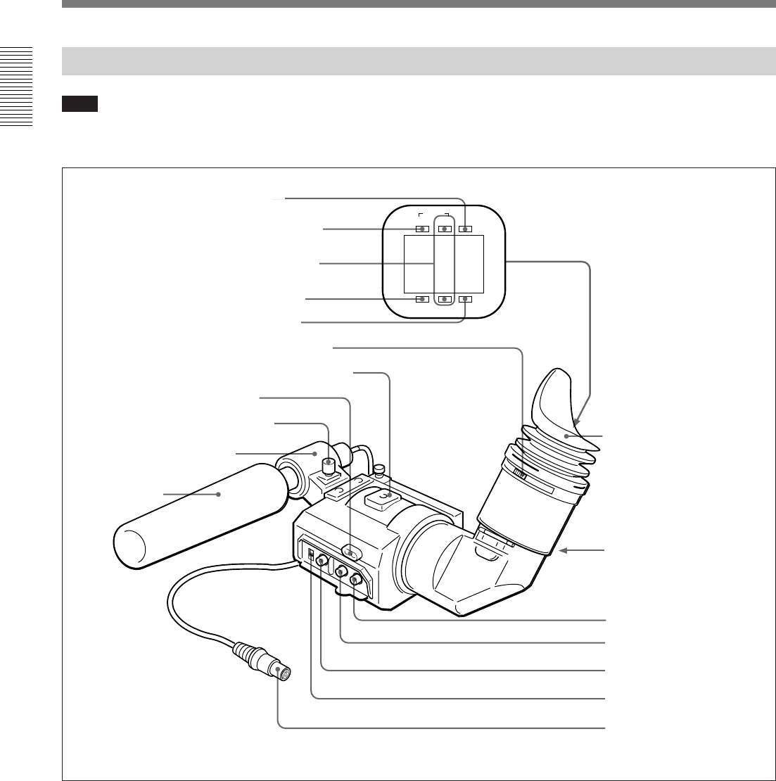
DXF-701WS/701WSCE Viewfinder
SHUTTER GAIN UP
TAKE BATTREC
TALLY
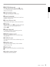
1 BATT indicator
2 TAKE/TALLY indicator
3 REC/TALLY indicators
4 SHUTTER indicator
5 GAIN UP indicator
6 Eyepiece focusing knob
7 Accessory fixing screw hole
8 Tally lamp
9 Eyepiece release catch
0 BRIGHT control
!¡ CONTRAST control
!™ PEAKING control
!£ TALLY switch
!¢ Viewfinder connector
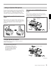
Microphone holding screw
Microphone holder
Microphone
a)
Eye cup
a) Not supplied with the optional DXF-701WS/701WSCE
1 BATT (battery) indicator (red)
This indicates when the battery capacity is low.
2 TAKE/TALLY indicator (orange)
When using the ClipLink function while shooting, this
indicator lights when the TAKE button (6 on page
11) has been pressed to set a Mark IN point and goes
out when a Mark OUT point is set.
Note
You can switch the scan size of the DXF-701WS/
701WSCE in accordance with the aspect ratio
selected on the camera or camcorder. However, it
operates in 4:3 mode when used on the DSR-300/
300P.
3 REC/TALLY (recording/tally) indicators (red)
• From the time when you press the VTR button (9 on
page 11 and !∞ on page 27) on the lens or
camcorder, this flashes until recording starts, then
stays on continuously during recording.
• This is also used to indicate a fault. (See page 115.)
• The lower indicator can be disabled by menu setting.
(See page 86.)