


Chapter 1 Overview
Chapter 1 Overview 23
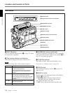
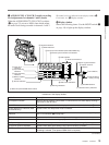
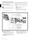
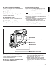
3 SHIFT button
When setting time code and user bit values, or at menu
setting, keep pressing this button to select a digit. The
selected digit will start blinking.
In other case, keep pressing this button to show the
date (when the DISPLAY switch (6 on page 17) is
set to U-BIT) and time (when the DISPLAY switch is
set to TC) instead of time value.
For time code and user bit settings, see page 71.
On how to use the SHIFT button for menu settings, see
“Setting on the VCR Section —VCR Menu” (page 117).
4 AUDIO SELECT (CH-1/CH-2) (audio recording
level adjustments manual/auto selection for
channels 1 and 2) switches
These select the audio recording level adjustment
method.
AUTO: Use the AGC (automatic gain control) circuit
to automatically adjust the audio level.
MAN: Enables users to manually adjust the AUDIO
LEVEL (CH-1/CH-2) knobs (7 on page 19) for
each channel. Select AUTO if excess input levels
are likely to occur.
5 AUDIO IN (CH-1/CH-2) (audio input selection
for channels 1 and 2) switches
These select the input signals to channels 1 and 2.
FRONT: Signals from the microphone connected to
the MIC IN +48 V connector.
VJ MIC: Signals from the remote control unit with
microphone connected to the REMOTE connector
2
WIRELESS: Signals from the WRR-855A
synthesized tuner connected to the WRR
connector via the CA-WR855 Camera Adaptor.
REAR: Signals from a microphone or external
equipment connected to the AUDIO IN (CH-1/
CH-2) connectors.
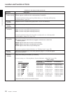
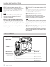
6 Lithium battery compartment
Insert the supplied CR2032 Lithium Battery.
On how to fit the lithium battery, see page 37.
7 MONITOR OUT (monitor output)
CHARACTER switch
Set ON to superimpose text information on the
monitor output.
Note
Set this switch ON when using the freeze mix
function.
8 TC (time code) mode switch 2
Sets the mode for advancing time code values when
the TC mode switch 1 9 has been set to PRESET.
F-RUN: The time code advances continuously
whether or not the camcorder is recording. Use
this setting to align the time code value with real
time.
SET: Use this setting to set the time code or user bit
value.
R-RUN: The time code value advances only during
recording. Use this setting to have consecutive
recordings on the tape.
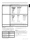
Note for the DSR-370/570WS
There are two time code frame modes: drop-frame
(DF) mode and non drop-frame (NDF) mode. This
product is shipped with drop-frame mode selected.
For details on switching between drop-frame mode and non
drop-frame mode, see “Selecting Frame Mode (DF/NDF)
for Time Code (for DSR-370/570WS only) —Menu 204”
(page 119).
For details on drop-frame mode and non drop-frame mode,
see “Drop-frame mode (for DSR-370/570WS only)” on page
74.
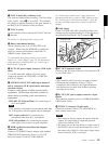
9 TC (time code) mode switch 1
Selects between resetting the time code value or
continuing from the time code value at the end of the
previous recording.
PRESET: This starts recording time code values on
the tape from the currently set value.
REGEN: During back space editing, this reads the
tape’s current time code value and sets the time
code to record starting from that value. The time
code value is advanced in R-RUN mode
regardless of the setting on TC mode switch 2 8.
DATE/TIME: This synchronizes the time code to
the real time clock set in the VCR menu (see page
119). In this case the time code of the DSR-370/
570WS is recorded in DF (drop-frame mode).
Note
If the ClipLink function is set to on (meaning ClipLink
shooting is allowed) in menu 211 and CONT is
displayed in the display window, regardless of the
setting of this switch, the time code generator
automatically enters the REGEN mode at recording.
(When not performing ClipLink shooting, set the
ClipLink function to oFF (see page 123)).