


Chapter 2 Location and Function of Parts
2-16 Chapter 2 Location and Function of Parts
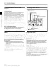
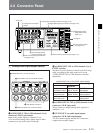
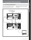
2-2 Connector Panel
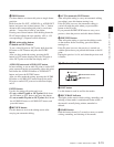
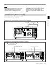
2 Analog video input/output section
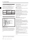
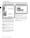
1 REF. (reference) VIDEO INPUT connectors
(BNC type) and 75Ω termination switch
Input a reference video signal. Input a three-valued
(positive and negative) sync signal, a video signal with
chroma burst (VBS) or a monochrome video signal
(VS). When using the loop-through connection set the
switch to the OFF position, and otherwise to the ON
position.
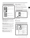
2 COMPONENT VIDEO OUTPUT connectors
(BNC type)
These connectors output analog component video
signals (Y/R–Y/B–Y).
3 COMPOSITE VIDEO OUTPUT connectors
(BNC type)
These connectors output analog composite video
signals.
When the setting of F4 (CHARA) in function menu
page 4 is ON, connector 3 (SUPER) outputs a signal
with superimposed time code, menu settings, alarm
messages, and other text information.
75Ω
REF INPUT
INPUT 1125/525
OFF ON
VIDEO OUTPUT
COMPOSITE COMPONENT
3
(SUPER)
2
1
B-Y
R-Y
Y
1 REF.VIDEO INPUT connectors
and 75Ω termination switch
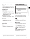
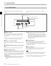
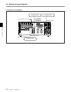
3 Digital audio input/output section
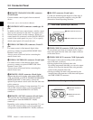
1 AUDIO INPUT (AES/EBU) connectors (BNC
type)
Input two sets (4 channels: CH1/2 and CH3/4) of AES/
EBU format digital audio signals.
2 AUDIO OUTPUT (AES/EBU) connectors (BNC
type)
Output a maximum of 4 sets (8 channels: CH1/2, CH3/
4, CH5/6, CH7/8) of AES/EBU format digital audio
signals.
However, the HDW-2000 supports 2 sets only (4
channels: CH1/2, CH3/4).
AUDIO INPUT(AES/EBU)
CH1/2 CH3/4
AUDIO OUTPUT(AES/EBU)
CH1/2 CH3/4 CH5/6 CH7/8
1 AUDIO INPUT (AES/EBU) connectors
2 AUDIO OUTPUT (AES/EBU) connectors
2 COMPONENT VIDEO
OUTPUT connectors
3 COMPOSITE VIDEO
OUTPUT connectors