


Chapter 2 Location and Function of Parts
2-18 Chapter 2 Location and Function of Parts
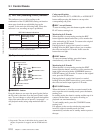
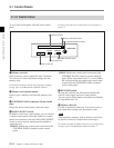
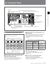
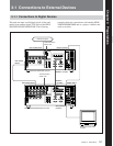
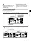
2-2 Connector Panel
1 REMOTE 2 PARALLEL I/O(50P) connector
(D-sub 50-pin)
Connect remote control signals from an external
device.
For details, refer to the Installation Manual.
2 CONTROL PANEL connector (round type, 10-
pin)
In addition to the lower control panel, a similar control
panel can be connected to this unit. To connect such a
second control panel, use this connector. When two
control panels are connected, use the PANEL SELECT
switch on the switch panel (see page 2-14) to specify
which control panel will control this unit.
3 VIDEO CONTROL(15P) connector (D-sub 15-
pin)
For remote control of the internal digital video
processor, connect an optional BVR-50/50P Video
Remote Control Unit.
Always power off this unit before connecting the
remote control unit.
4 VIDEO CONTROL(9P) connector (D-sub 9-pin)
For remote control of the internal digital video
processor, connect an optional HKDV-900 Video
Remote Control Unit.
Always power off this unit before connecting the
remote control unit.
5 REMOTE 1-IN(9P) connector (D-sub 9-pin)
When using this unit together with another HDCAM
VTR, and a BVE-series BVE-700/900/910/2000/9000/
9000P/9100/9100P or other editor, connect the
optional 9-pin remote control cable from the other unit
to this connector.
Depending on the setting of setup menu item 211, you
can use this connector alone, or in a loop-through
configuration with the REMOTE 1-OUT(9P)
connector.
6 REMOTE 1-OUT(9P) connector (D-sub 9-pin)
This provides the loop-through output for remote
control signals from the REMOTE 1-IN(9P)
connector.
Depending on the setting of setup menu item 211, you
can use this connector alone, or in a loop-through
configuration with the REMOTE 1-IN(9P) connector.
7 RS-232C connector (D-sub 9-pin)
Use this for monitoring and diagnosis of the state of
this unit from an external computer, using the ISR
(Interactive Status Reporting) function.
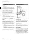
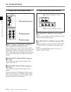
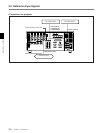
7 Time code input/output section
1 TIME CODE IN connector (XLR 3-pin, female)
To record time code from an external device, input a
time code signal from the time code output connector
of the other device.
2 TIME CODE OUT connector (XLR 3-pin, male)
This outputs a time code according to the operating
state of the unit, as follows:
•During playback: the playback time code
By setting setup menu item 606, you can also output
the time code from the internal time code generator
locked to the playback time code.
•During recording: the time code generated by the
internal time code generator or the time code input to
the TIME CODE IN connector.
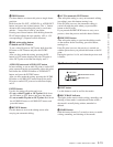
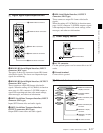
8 Audio monitor signal output section
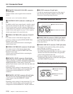
TIME CODE
IN OUT
1 TIME CODE IN connector
2 TIME CODE OUT connector
MONITOR OUTPUT
RL
1 MONITOR OUTPUT R
connector
2 MONITOR OUTPUT L
connector