


Chapter 2 Location and Function of Parts
Chapter 2 Location and Function of Parts 2-17
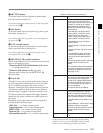
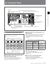
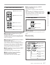
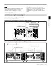
4 Digital signal input/output section
1 HDSDI (HD Serial Digital Interface) INPUT
connectors (BNC type)
The upper of these two connectors inputs HD format
video/audio signals. The lower one outputs the input
signals for monitoring.
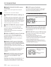
2 HDSDI (HD Serial Digital Interface) OUTPUT
connectors (BNC type)
These connectors output HD format video/audio
signals. When the setting of F4 (CHARA) in function
menu page 4 is ON, connector 3 (SUPER) outputs a
signal with superimposed time code, menu settings,
alarm messages, and other text information.
3 SDTI (Serial Data Transport Interface) INPUT
connector (BNC type)
Inputs SDTI format video and audio signals.
4 SDTI (Serial Data Transport Interface)
OUTPUT connectors (BNC type)
Output SDTI format video and audio signals.
SDI
HDSDI
INPUT
OUTPUT
OUTPUT
OUTPUT
1
2
3(
SUPER
)
1
2
3(
SUPER
)
SDTI
INPUT
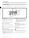
INPUT MONITOR
1
2
1 HDSDI INPUT connectors
3 SDTI INPUT connector
4 SDTI OUTPUT connectors
5 SDI OUTPUT connectors
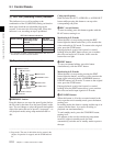
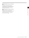
5 SDI (Serial Digital Interface) OUTPUT
connectors (BNC type)
These connectors output D1 format video/audio
signals.
When the setting of F4 (CHARA) in function menu
page 4 is ON, connector 3 (SUPER) outputs a signal
with superimposed time code, menu settings, alarm
messages, and other text information.
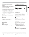
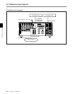
5 Power supply section
1 AC IN connector
Use the optional power cord to connect this to an AC
outlet.
2 Ground terminal
Connect this to ground.
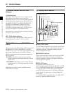
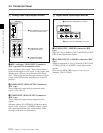
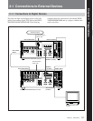
6 External device connectors
1 AC IN connector
2 Ground terminal
REMOTE 1-IN(9P)
CONTROL PANEL
REMOTE 2 PARALLEL I/O(50P)
VIDEO CONTROL (15P)
REMOTE 1-OUT(9P)
RS232C
VIDEO CONTROL (9P)
1 REMOTE 2 PARALLEL
I/O(50P) connector
2 CONTROL PANEL
connector
3 VIDEO CONTROL(15P)
connector
4 VIDEO CONTROL(9P)
connector
5 REMOTE 1-IN(9P)
connector
6 REMOTE 1-OUT(9P)
connector
7 RS-232C connector
2 HDSDI OUTPUT connectors