Parts Identifications
22
Overview
1. SHOT TRANSITION operation block
(page 82)
2. TC/U-BIT/DURATION (time data
selection) button (page 70, page 98)
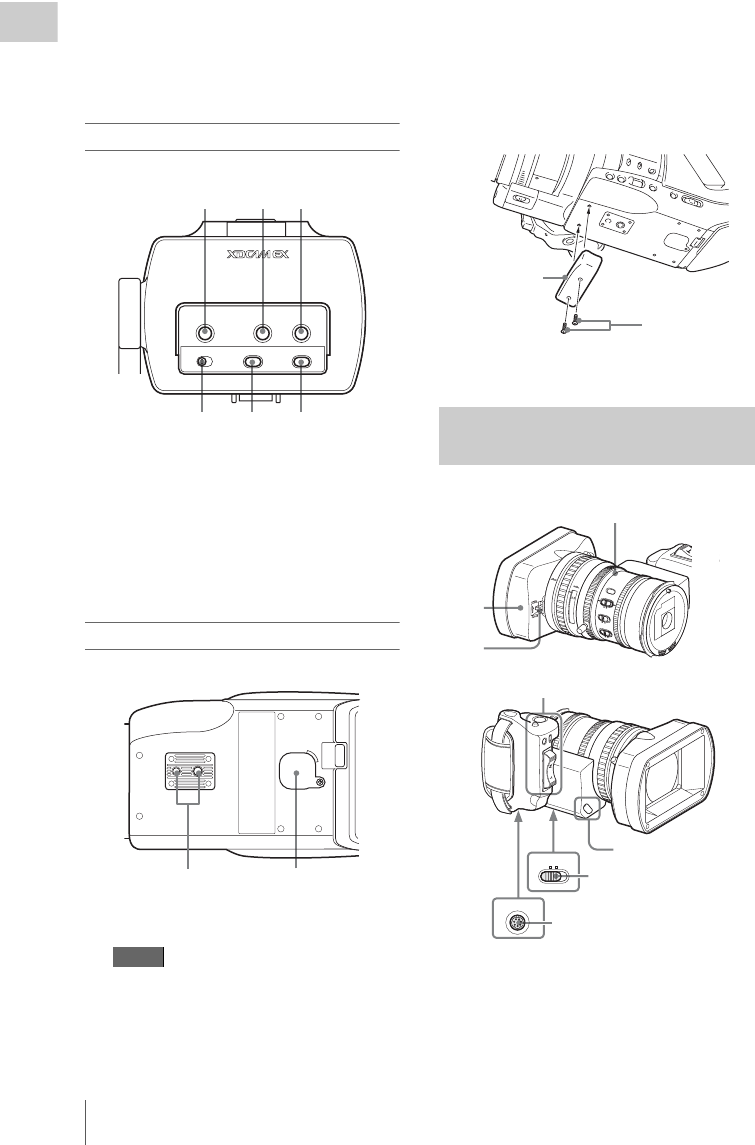
Viewfinder control panel
1. PEAKING control (page 65)
2. CONTRAST control (page 32)
3. BRIGHT control (page 32)
4. MIRROR IMAGE switch (page 33)
5. DISPLAY/BATT INFO button (page 25)
6. ZEBRA button (page 57)
Bottom
1. Tripod receptacles
Check that the size of the hole matches the
screw of the tripod. If they do not match, the
camcorder cannot be attached to the tripod
securely.
When attaching to a tripod
Use the supplied bottom plate to stabilize the
camcorder. Remove two screws from the
bottom of the camcorder and attach the
bottom plate using the two supplied screws
(M2×6).
2.Backup battery holder (page 149)
1.Lens hood
2.Lens cap open/close lever (page 50)
3.ZOOM switch (page 62)
4.LENS REMOTE connector (page 64)
Note
MIRROR IMAGE
OFF ON
DISPLAY/BATT INFO
ZEBRA
PEAKING CONTRAST BRIGHT
6
123
4
5
12
Zoom Lens VCL-614B2X
(Supplied)
Bottom plate
M2×6 screws
1
5
25
4
0
8
1
.
2
10
3
1
0
m
m
5
1
0
3
0
f
t
1
5
5
.
8
8
5
.
6
4
2
.8
1.9
16
C
M
A
N
U
A
U
T
O
M
A
N
U
A
U
T
O
P
U
S
H
A
F
F
O
C
U
S
IRIS
S
T
E
A
D
Y
S
H
O
T
A
F
F
u
l
l
M
F
M
A
C
R
O
O
F
F
O
N
EXPANDED
FO
CUS
REC
REVIEW
RELEASE
START/
STOP
MANU SERVO
ZOOM
LENS
REMOTE
1
2
3
4
Cover of the lens
control block (See
“Note” below.)
Controls on the grip
(page 23)
Lens control block (page 23)


