


GB
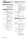
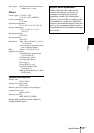
28 Specifications
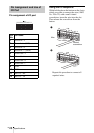
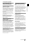
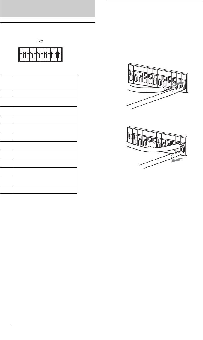
Pin assignment of I/O port
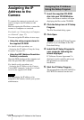
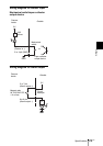
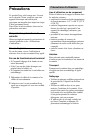
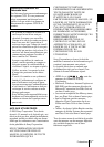
Using the I/O receptacle
While holding down the button on the slot to
which you want to connect the wire (AWG
No. 28 to 22) with a small slotted
screwdriver, insert the wire into the slot.
Then release the screwdriver from the
button.
Repeat this procedure to connect all
required wires.
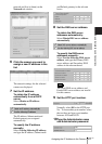
Pin Assignment and Use of
I/O Port
Pin
No.
Pin name
1 Sensor In 1 +
2 Sensor In 1– (GND)
3 Sensor In 2 +
4 Sensor In 2 – (GND)
5 Alarm Out 1 +
6 Alarm Out 1 –
7 Alarm Out 2 +
8 Alarm Out 2 –
9 GND
10 GND
11 RS232C · RX
12 RS232C · TX
121110
987654321
I/O
12 11 10 9 8 7 6 5 4 3 2 1
I/O
12 11 10 9 8 7 6 5 4 3 2 1
1
2
Slotted
screwdriver
Wire