


11
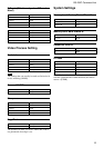
RS-232C Command List
1
2
3
4
5
6
7
8
9
10
11
12
Precautions to be Observed
When Using RS-232C
Commands
• When the unit is shipped from the factory, the RS-
232C input item is set to [OFF]. To send RS-232C
commands to the camera, flip the DIP-switch to
[ON]. For details, refer to “Setting the RS-232C
switch” in the next column.
Changing the setting of the RS-232C switch falls
under the heading of dismantling the camera, and
is outside the scope of the warranty. To change the
setting, request assistance from the dealer from
whom you purchased your camera.
• When toggling the RS-232C Input/Output function
on and off, and when connecting the camera and a
host computer, be sure perform any operations only
after shutting off the power of both the camera and
the host computer.
• When controlling the camera using the RS-232C
feature, the DIP switches on the camera and the R/B
adjustment volume settings are disabled.
• Use only the Sony DC-700/700CE power adaptors.
The DC-77RR/77RRCE, DC-777/777P, CMA-D2/
D2CE, and CMA-D2MD adaptors cannot be used.
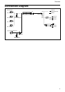
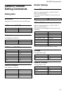
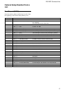
• Keep in mind the following with respect to the RS-
232C TXD and RXD connectors:
– Do not allow the voltage applied to exceed a
margin of +/– 10V with the RXD (pin 11 of the 12
multi-connector).
– The signal level output from the TXD (pin 10 of
the 12 multi-connector) is within +/– 5.4V (TYP).
Do not apply external voltage.
RXD
TXD
Setting the RS-232C
Switches
Warning
Be aware that changing the setting of the RS-232C
switches falls under the heading of dismantling the
camera, and anything beyond this change of settings,
carried out by a Sony-authorized repair department
(company), is outside the scope of the warranty.
Notes
• Be sure to make these changes only after turning off
the power to the camera.
• In order to keep dust from adhering to the light-
receptor surface of the CCD, attach the lens mount
cap, etc., beforehand.
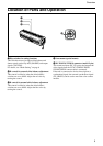
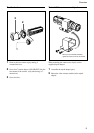
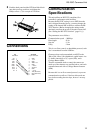
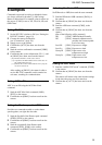
1 Detach the 12-pin cable from the camera.
2 Using a Philips screwdriver, remove the Philips
screws (7) from the camera.
At this point, the head block may fall out because
of elasticity of wires attached to the CCD head
block. Take care to avoid this.
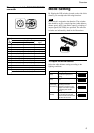
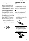
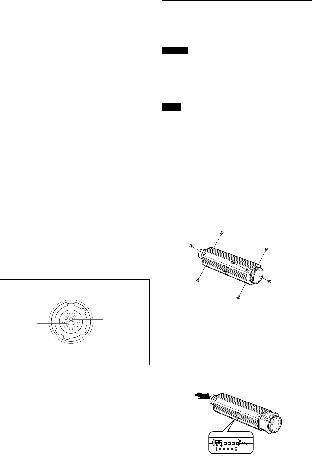
3 Push the rear panel to which the 12-pin connector
is attached about 3 mm into the frame of the
camera. The hidden RS-232C DIP switches will
become visible in the little window provided to
carry out DIP switch operations.
4 Switch both of the last two switches on the left end
of the row to the down position.