


6
Overview
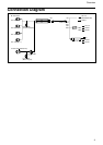
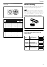
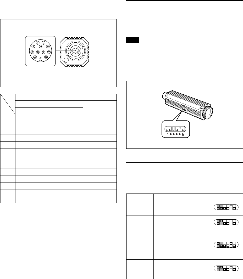
Pin assignment of the DC IN/SYNC/VIDEO
connector
Signal
Sync signal types
External Sync signal
Internal Sync
Pin No.
HD,VD VS Input
signal
1 GND (Earth) GND (Earth) GND (Earth)
2 +12V +12V +12V
3
VBS/Y Output (Earth) VBS/Y Output (Earth) VBS/Y Output (Earth)
4
VBS/Y Output (signal) VBS/Y Output (signal) VBS/Y Output (signal)
5 HD Input (Earth) - -
6 HD Input (signal) - -
7 VD Input (signal) VS Input (signal) -
8 GND (–/C) GND (–/C) GND (–/C)
9 –/C Output (signal) –/C Output (signal) –/C Output (signal)
10 RS-232C (TXD) *
11 RS-232C (RXD) *
12 VD Input (Earth) VS Input (Earth) GND
RS-232C (Earth)
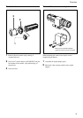
Mode Setting
By flipping the DIP switches located on the side of this
camera, you can adjust the following functions.
Note
Each switch is assigned to the function. The switches
that should be set for a certain function (white balance,
shutter speed, AGC (Auto Gain Control), switching of
output signals(Y/C/VBS)) are specified. The effective
switches are indicated by shade in the illustrations.
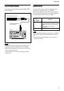
To Adjust the white balance
Select the white balance setting according to the
lighting conditions.
Lighting condition DIP switch setting
For indoor shooting under
incandescent light (factory
setting).
For outdoor shooting on sunny
days.
The white balance is adjusted
according to the color
temperature transition of the
subject. This mode is suitable
for shooting with variable
lighting.
Select this position when you
want to adjust the red color
with the R control and the blue
color with the B control.
3200K
(fixed)
5600K
(fixed)
ATW
(auto tracing
white balance)
MAN
(manual)
1 ····6
1 ····6
1 ····6
1 ····6