


3-8 Operator's Manual LDK 23HS mkII - HS Camera System Configurations
VF
R- Y
B- Y
VF
I NDICAT IONS
TRIAX
EXT SIGNAL
SELECT ION
VF SIGNAL
SELECTION
or RET button
on the lens
control signal
TRANSMITTER/
RECEI VER
COMPONENT
MATRI X
Y
R
B
G
TRANSMI TTER/
RECEI VER
ADC +
Digital
Vi deo
Decoder
R- Y
B-Y
Y
control signal
control signal
control signal
control signal
DI GITAL VIDEO PROCESSOR
MONITORI NG + VIEWFINDER
EXT1
EXT2
Y
VF-OUT
EXT
LOCAL
EXT. VF
OFF
ON
control signal
PI P
MON VID OUT
Y
R
G
B
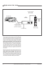
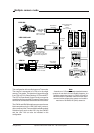
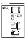
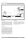
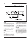
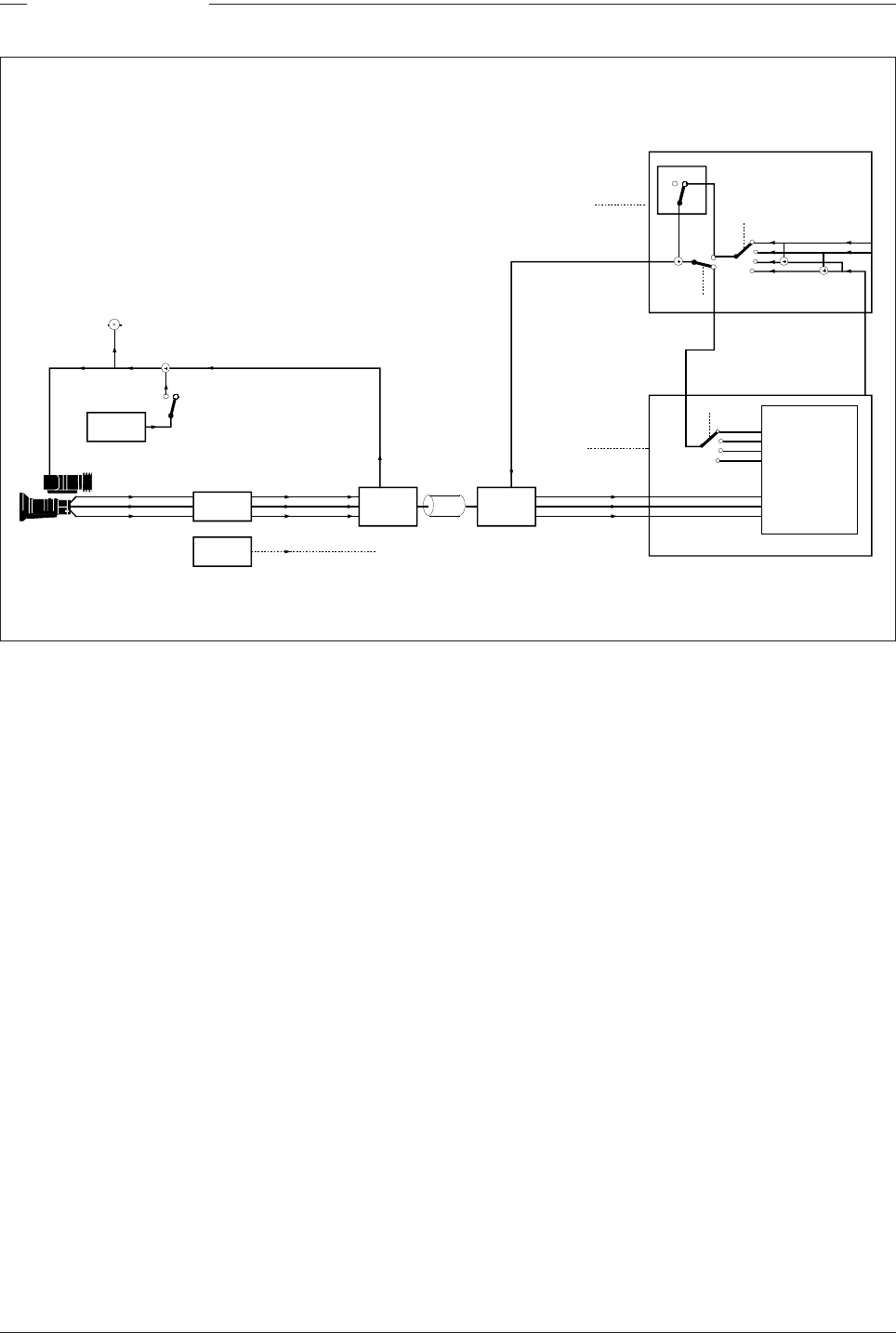
Video Routing
Main video path
When the camera is used in the triax mode, the R, G
and B video signals from the sensors are first subjected
to video processing and then pass to the multiplexer/
transmitter section which sends Y, R-Y and B-Y to the
CPU via the triax cable. The R, G and B video signals
are available for the studio as outputs on the rear of the
CPU.
Viewfinder video
The normal signal displayed in the viewfinder is the Y
signal. This is derived from the R, G and B video
signals from the video processing circuits. Additional
information is added to the viewfinder signal to provide
superimposed text and graphics. The video signal for
display in the viewfinder can be selected from the
above mentioned Y signal or an external 1 or external
2 video signal. The external 1 and 2 video signal are
input from the studio system to the rear of the CPU and
are transmitted via the triax cable to the camera. The
Y, external 1 and external 2 video signals can be
viewed separately, or Y mixed with external 1 or 2.
Output signals
The camera has four video output connectors: two on
its right side and two on the backpanel. The external
output connector carries the external signal from the
CPU. The monitoring out connector carries the signal
which is displayed in the viewfinder.