


Adjustments Technical Manual LDK 20(S) - Studio Camera 4-39
Encoder Board PAL
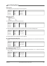
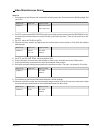
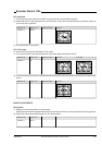
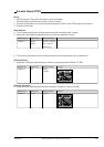
B-Y amplitude
11. On the encoder board disconnect MP7 from ground and connect MP8 to ground.
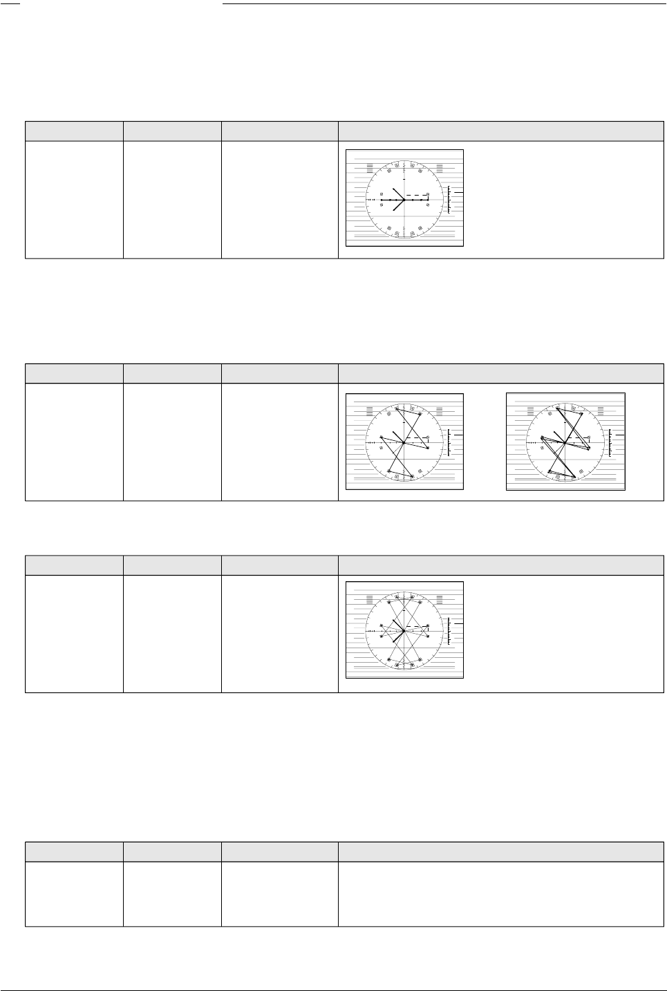
12. Adjust with the B-Y gain potentiometer until the colour vector dots correspond with the indication marks on
the U-axis of the graticule.
Measure at: Adjust with: Required result: Correct:
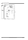
CVBS out ZR202
20
40
R
60
80
0.7
100
120
20
43
0.3
g
YL
MG
cy
b
Byl
G
r
CY
mg
75
100
U
V
0
0
5
-5
% VOLT
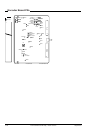
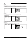
13. Disconnect MP8 from ground.
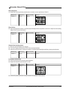
R-Y / B-Y phase
14. Switch vectorscope from Standard to PAL mode.
15. If the vector dots are not superimposed on each other adjust the phase with L8.
Measure at: Adjust with: Required result: Correct: Incorrect:
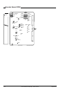
CVBS out L8
20
40
R
60
80
0.7
100
120
20
43
0.3
g
YL
MG
cy
b
Byl
G
r
CY
mg
75
100
U
V
0
0
5
-5
% VOLT
20
40
R
60
80
0.7
100
120
20
43
0.3
g
YL
MG
cy
b
Byl
G
r
CY
mg
75
100
U
V
0
0
5
-5
% VOLT
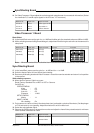
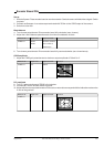
16. Switch vectorscope from PAL to Standard mode and check that the vector dots are exactly in the vectorscope
boxes.
Measure at: Adjust with: Required result: Correct:
20
40
R
60
80
0.7100
120
20
43
0.3
g
YL
MG
cy
b
Byl
G
r
CY
mg
75
100
U
V
0
0
5
-5
% VOLT
BURST ADJUSTMENTS
Burst phase
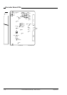
17. Measure in second quadrant of vectorscope.
Adjust the input sensitivity potentiometer of the vectorscope so the burst vectors just touch the circle graticule.
18. Adjust the burst phase potentiometer for 90° phase output.
Measure at: Adjust with:
CVBS out ZR211