


Adjustments Technical Manual LDK 20(S) - Studio Camera 4-45
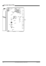
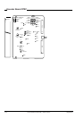
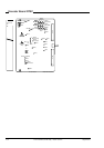
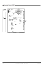
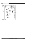
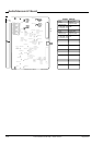
Encoder Board NTSC
I amplitude
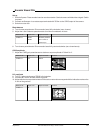
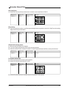
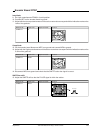
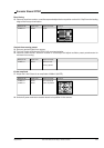
9. Set I gain potentiometer ZR205 in its mid-position.
10. Connect MP7 on the encoder board to ground.
11. Adjust with the chroma potentiometer until the colour vector dots correspond with the indication marks on the
I-axis of the graticule.
Measure at: Adjust with: Required result: Correct:
CVBS out R4
20
40
R
60
80
12.5%
100
120
20
40 100%
YL
MG
B
G
CY
75
100
I
Q
75%
0
5
-5
IRE
0%
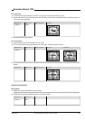
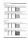
Q amplitude
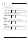
12. On the encoder board disconnect MP7 from ground and connect MP8 to ground.
13. Adjust with the Q gain potentiometer until the colour vector dots correspond with the indication marks on the
Q-axis of the graticule.
Measure at: Adjust with: Required result: Correct:
CVBS out ZR202
20
40
R
60
80
12.5%
100
120
20
40 100%
YL
MG
B
G
CY
75
100
I
Q
75%
0
5
-5
IRE
0%
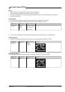
14. Disconnect MP8 from ground and check that the SMPTE colour bar signal is correct.
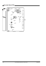
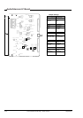
SMPTE bar shift
15. Adjust the SMPTE shift so that the PLUGE signal is within the red bar.
Measure at: Adjust with: Required result: Correct:
CVBS out ZR212
0%
10
90
100
Red bar
PLUGE signal
>50mV
10µS