


10
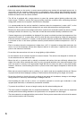
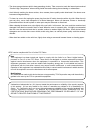
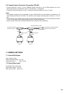
6.1. Precautions When Installing the Camera
• Insulate the joint of the camera video output cable and the coaxial cable from other equipment by wrapping
the (vinyl) insulating tape around it. Also, install such cables taking care that they do not contact metal stuff
close to them.
• Avoid install the camera cable in close proximity to other cables of electric products, such as fluorescent
lamps. Failure to do this could downgrade the picture quality.
• Installing the camera near the strong electric or magnetic field produced by television transmitting antennas,
motors or transformers could distort or shake the monitor screen. In such cases, install the cables in the
sheet steel cable piping.
• Before applying the power to the camera, be sure to complete all connections between the camera and
related equipment.
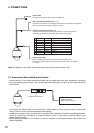
System controller,
Multi switcher, Monitor
Insulate with vinyl tape.
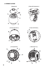
1
2
3
4
5
6
7
8
Power cable
Connects to the power supply. (24V AC 50/60 Hz)
Alarm input/output terminal (No. 1 - 5)
Connects to the sensor of no-voltage make contact or the external equipment
that can be controlled using the auxiliary output.
Camera control terminal (No. 6 - 8)
Connects to cables from the Remote Controller or other camera when
controlling the camera using the RS-485 communications line.
Video output cable
When controlling with use of the RS-485 communications line,
connect this output cable to the video input terminal of the multi-switcher
or monitor.
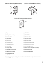
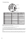
Wire color Dot color Terminal name
Orange Black GND
Orange Red Alarm input 3 (AL3)
Yellow Black Alarm input 2 (AL2)
Yellow Red Alarm input 1 (AL1)
Green Black Auxiliary output (AUX)
Green Red GND
Gray Black RS485 (–)
Gray Red RS485 (+)
Note: The length of power cable, video output cable and multi wick cable is about 1.8 m.
6. CONNECTIONS