


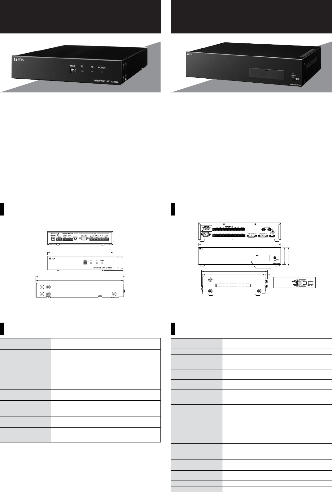
C-IF500
INTERFACE UNIT
C-AL80
ALARM UNIT
SPECIFICATIONS (H/L)SPECIFICATIONS
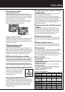
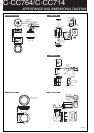
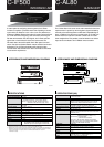
APPEARANCE AND DIMENSIONAL DIAGRAM
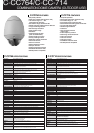
APPEARANCE AND DIMENSIONAL DIAGRAM
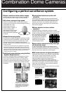
A useful option for configuring camera systems, the C-IF500
functions as a splitter. It provides control over expanding a camera
system when the distance is over 1.2km (max. 3km) between the
dedicated C-RM500 Remote Controller and system cameras linked
to it. It will also allow configuring a star connection. Receiving the
RS-485 communication line serial signals, the C-IF500 splits the
signals into 4-channel data for slave units and converts into
RS-232C data to be used for public line or fiber optics communi-
cation. Data communication between master and slave terminals is
bidirectional. The C-IF500 also allows easily setting the data
communication data transfer rate in four increments via DIP switch
to suit network requirements.
Unit: mm
Unit: mm
44
46
210
279.8
284.1
Power Source 12 V DC
Current Consumption 100 mA
External Control Master: RS-485, screwless connector
terminating resistance (100 Ω) switch ON/OFF
Slave(*
1
): 4 channel, RS-485, screwless connector
RS-232C, D-sub connector (9-pin, male)
Display Power LED indicator, communication LED indicators
(TX, RX)
Maximum Cable RS-485: 1.2 km (*
2
)
Distance RS-232C: 10 m
Communication Speed 4800 bps, 9600 bps, 19200 bps, 38400 bps
Operating Temperature -10°C to +50°C
Operating Humidity Under 90% RH (no due condensation produced)
Finish Panel: Aluminum, black, 30% gloss, paint
Case: Pre-coated steel plate, 30% gloss, black
Dimensions 210 (W) x 46 (H) x 284.1 (D) mm
Weight 1.4 kg
Option Rack mounting bracket:
M-15B-BK (for rack mounting one C-IF500 unit)
MB-15B-J (for rack mounting two C-IF500 units)
(*
1
) Communications cannot be made between slave terminals.
Each slave terminal can connect up to 31 cameras. (except RS-232C port)
(*
2
) Applies to the system where the unit and combination camera are connected in a matched pair.
Represents the total of connected cable distances if multiple combination cameras or Interface
units are connected in the system (when the CPEV-S cable thicker than 0.65 mm
in diameter is used).
Power Source H: 230 V AC, 50/60 Hz
L: 120 V AC, 50/60
Power Consumption under 3 W
Alarm/Remote Input 32 channels, no-voltage make contact input, open
voltage: 5 V DC, short-circuit current: max. 5 mA, M3
screw terminal, distance between barriers: 7.62 mm
Control Input/Output 1 channel, RS-232C, D-sub connector (9 P, male)
(only valid for master unit), fixed to 38,400 bps
Master/sub Connection 2 channels, RS-485, maximum cable length: 1200m,
Terminal DIN connector (5 P)
Alarm Reset Input 1 channel, no-voltage make contact input, open
voltage: 5 V DC, short-circuit current: max. 5 mA, D-sub
connector (25 P)
Setting Switches Master/Slave: 3-bit DIP switch
(Selection of Master or Slave 1—7)
Alarm/Remote: 1-bit DIP switch
(Alarm/Remote selection)
Alarm time: 1-bit DIP switch (Edge/Level selection)
RS-485 terminal: Rear-mounted slide switch (RS-485
termination, Enable/Disable selection)
Application Indoor use
Operating Temperature 0°C to +50°C
Finish Panel: Aluminum extrusion, black, 30% gloss
Case: Pre-coated steel plate, black, 30% gloss
Dimensions 420 (W) × 96.6 (H) × 335.8 (D) mm
Weight 3.6 kg
Accessory DIN plug × 2, RS-232C cable (2 m) × 1, D-sub
connector (25 P) × 2, Power cord (2 m) × 1
Option Rack mounting bracket: MB-23B
Application Model Remote controller: C-RM500
The C-AL80 Alarm Unit serves as the main controller for the alarm
requirements of a system by converting alarm signals initiated by
externally connected equipment into RS-232C-compatible signal
data. In addition to its 32 alarm or remote inputs, the C-AL80 can
also be linked to a maximum of 8 other C-AL80 units in master/
slave configurations. This provides a total of 256 alarm or remote
inputs to be transmitted to the C-RM500 remote controller.
88.4
96.6
420
335.8
319.8
11
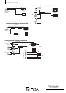
Front cover
Enlarged figure for
the inside of a front cover