


12
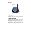
3. Reset Button
Reset will be initiated when the reset button is pressed once, and
Power LED begins to flash.
Factory Reset will be initiated when the reset button is pressed
continuously for three seconds or when Power LED begins to
light up. Release the reset button and the Power LED will begin
to flash, indicating the Wireless Internet Camera is changing to
factory reset. When factory reset is completed, the Wireless
Internet Camera will be set to default on channel 11 and SSID is
set as “NULL String” (This default setting will let the Wireless
Internet Camera connect to ANY access point on the
infrastructure network). The IP address will also return to the
default setting as 192.168.0.30.
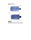
4. I/O Connector
The camera provides the I/O connectors on the rear panel (pin 1/2
are for RS485, pin 3/4 are for input, pin 5/6 are for output), which
provide the physical interface to send and receive digital signals
to a variety of external alarm devices. For more information, refer
to Appendix F, I/O Terminal Application.
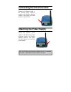
5. DC Power Connector
The DC power input connector is located on the Wireless Internet
Camera’s rear panel, and is labeled DC5V with a single jack
socket to supply power to the Wireless Internet Camera. Power
will be generated when the power supply is connected to a wall
outlet.