


13
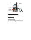
4. Power/Link LEDs
The upper LED indicates the camera is powered on with a steady
GREEN light.
The lower LED indicates the camera has good connection to LAN
/WLAN connectivity with a steady GREEN light. It begins
flashing to indicate the camera is receiving/sending data from/to
the LAN/WLAN.
5. Iris Level
This screw-knob is useful only when the DC-Iris lens is
connected to the camera. You can adjust the brightness of the
video images from the DC-Iris lens.
6. Network Cable Connector
This RJ-45 connector is used to connect the 10Base-T Ethernet or
100Base-TX Fast Ethernet network (which should be Category 5
twisted-pair cable). The port supports the NWay protocol,
allowing the camera to automatically detect or negotiate the
transmission speed of the network.
7. Reset Button
Reset will be initiated when this button is pressed. Factory Reset
will be initiated when this button is pressed continuously for five
seconds.
8. I/O Connector
The camera provides the I/O connectors on the rear panel (pin 1/2
are for input, pin 3/4, 5/6 are for output, pin 7/8 are for RS-485),
which provide the physical interface to send and receive digital
signals to a variety of external alarm devices.