


13
http://www.tyan.com
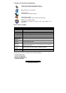
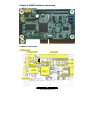
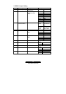
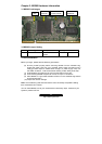
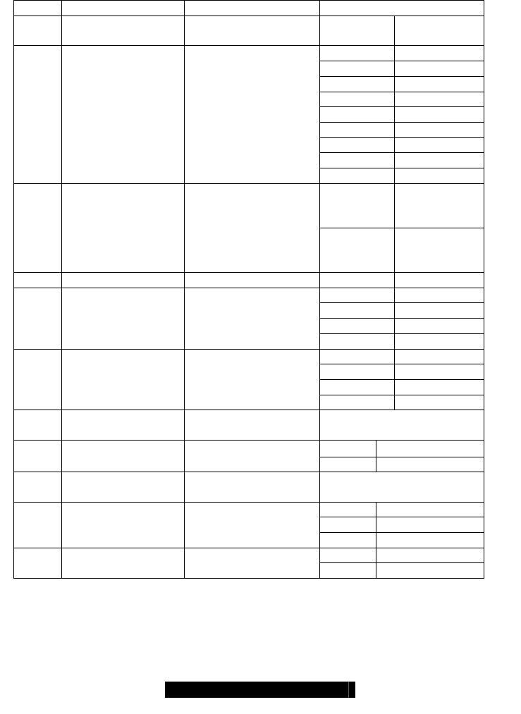
2.3 M3291 Jumper Setting
Label Header Type/Part Description Pin Layout
J1 HDR25X2_SVM_A SVM Edge
Connector A
Pin 1 DTR
Pin 2 DTR
Pin 3 TX
Pin 4 CTS
Pin 5 RX
Pin 6 RTS
Pin 7 NC
Pin 8 NC
J2 COM Port Signal remapped for
M/B COM2 (9Pin
GND)
Pin 9 GND
3-5,4-6
Close
BMC serial
connects to
J2
J3/J4 TX/RX Switch
RTS/CTS Switch
BMC Serial redirect
1-3,5-7,
2-4,6-8
Close
BMC serial
connects to
Serial MUX
J5 HUDI For ICE debug use
Pin 1 SDA
Pin 2 GND
Pin 3 SCLK
J6 IPMB Connector Connect with I2C0 of
BMC
Pin 4 NC
Pin 1 SDA
Pin 2 GND
Pin 3 SCL
J7 IPMB Connector Connect with I2C1 of
BMC
Pin 4 NC
JP1 HDR2 BOOT Mode Close to set BMC in Boot
Mode
Pin 1 GPIO56 JP2 HDR2 GPIO56
Pin 2 GND
JP3 HDR2 BMC Reset Close to Set BMC in
Reset
Pin 1 GND
Pin 2 5V
JP4 HDR3 5V power backup
Pin 3 GND
Pin 1 GPIO85 JP5 HDR2 GPIO85
Pin 2 GND