


VIKING TECHNICAL SUPPORT 1.800.908.0884
11
NOTE: This type on installation DOES NOT reverse the gate all the way back to
its limits when the edge sensor is obstructed. This installation is only to protect
against entrapment and to comply with UL325.
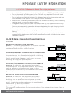
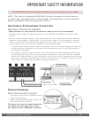
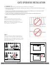
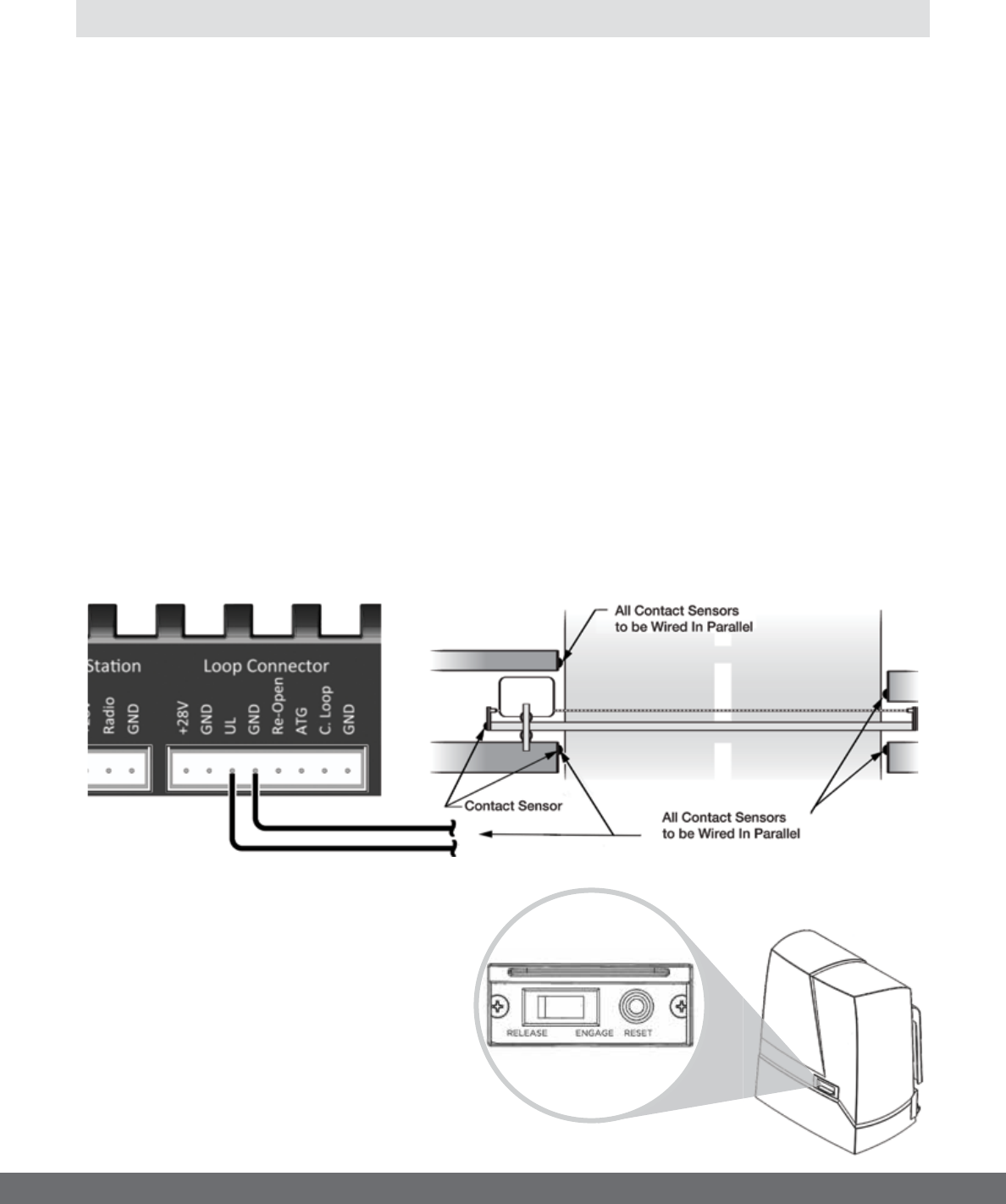
Secondary Entrapment Protection
Edge Sensor (contact sensor) Installation
•
Edge Sensors or like must be installed to reduce the risk of entrapment.
•
Use only Miller Edge 3-sided activation type MGR20 or MGS20 to comply with
UL325
•
One or more contact sensors shall be located on the inside and outside leading
edge of a swing gate. Additionally, if the bottom edge of a swing gate is greater
than 6 inches (152 mm) above the ground at any point in its arc of travel, one or
more contact sensors shall be located on the bottom edge.
1.
A hardwired contact sensor shall be located and its wiring arranged so that the
communication between the sensor and the gate operator is not subjected to
mechanical damage.
2.
A wireless contact sensor such as one that transmits radio frequency (RF) sig-
nals to the gate operator for entrapment protection functions shall be located
where the transmission of the signals are not obstructed or impeded by building
structures, natural landscaping or similar obstruction. A wireless contact sensor
shall function under the intended end-use conditions.
IMPORTANT SAFETY INFORMATION
! WARNING! Not Following these instructions may cause severe injury or death.
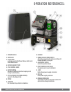
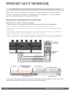
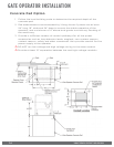
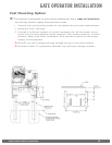
Manual Release
When manual operation is required:
1.
Lift the Access Door, located on the
front of the cover.
2.
Press the Manual Release Switch to
the “RELEASE” Position.
The gate can now be moved manually.
To resume normal operation, press
the switch to the “ENGAGE” position.