


VIKING TECHNICAL SUPPORT 1.800.908.0884
25
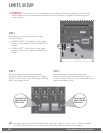
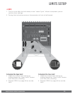
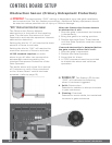
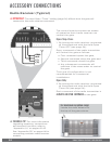
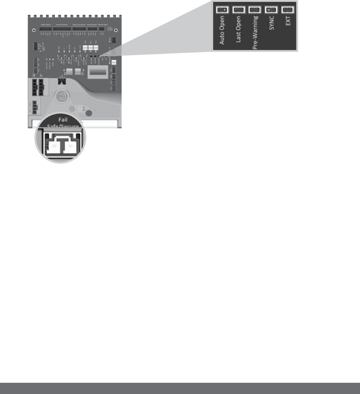
Initial Settings
NOTE:
Installing a shunt or jumper on the pins will activate the feature.
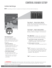
CONTROL BOARD SETUP
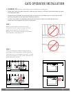
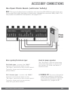
! IMPORTANT: Regardless of the power failure options chosen, the gate can be moved
manually with a relatively low amount of force by following the steps for “Manual
Release” as outlined at on page 11.
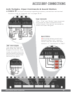
“Fail Safe/Secure”
During complete power
failure, including battery
power; determines the force
required to manually move
the gate.
•
Fail Safe Mode:
By removing the wire-
jumper plug from the “Fail
Safe/Secure” connector:
The gate can move
manually with a relatively
low amount of force.
•
Fail Secure Mode:
By inserting the wire-
jumper plug into the “Fail
Safe/Secure” connector:
The gate will not move
manually.
“Sync” Used only in conjunction with
the Viking Barrier gate operator model
B-12. Activating this feature allows for
synchronized operation with the B-12
operator. See page 33.
“Auto Open” - Power Failure Option
Opens the gate automatically during
power failure. Resumes normal operation
when power is restored.
“Pre-Warning” Initiates two options for
an audio or visual warning 3 seconds
prior to gate motion and will continue:
1.
Until gate reaches closed limit:
“Magnetic Lock” terminals provide a
contact between “COM” and “N.O”.
2.
While gate is moving:
“AUX. PWR” terminals provide 24VDC.
“EXT” Available for future developments.
“Last Open” - Power Failure Option
Opens the gate automatically when the
battery backup voltage is critically low.