


VIKING TECHNICAL SUPPORT 1.800.908.0884
41
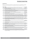
TROUBLESHOOTING
Solutions
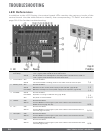
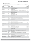
Begin the troubleshooting process by referring to the error messages on the LCD
Display and/or the Status LEDs on the control board. Use pages 36-40 to identify
the Troubleshooting Reference # (TS Ref#) then reference the table below.
TS Ref# CHECK Page Ref#
1
Check that the high voltage power supplied to “J-Box” is within range.
100v-120v or 200v-240v
pg. 18
2
Remove and check EMI Fuse for continuity.
pg. 3, 18
3
Check that the “Voltage Selector”, on the Modular Power Box, is set according
to the high voltage power supply. 115v AC or 230v AC
pg. 3, 18
4
Check that the “120VAC” switch is turned ON
pg. 3, 18
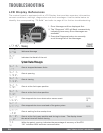
5 Check that the Power Harness is connected to the control board.
pg. 4, 18
6
Set the limit position.
pg. 20-21
7 Check Motor Fuse on the control board. pg. 4
8 Check that the “Manual Release” switch is turned to the “Engage” position. pg. 3, 11
9
Check the Status LEDs and LCD Display to determine if the control board is
receiving an input from any external devices or if the “ODS” has been triggered.
pg. 24, 26,
36-38
10
Remove the external devices from the control board to determine if the control
board is responding to an input or problem with the external device or wiring.
pg. 29-32,
36-37
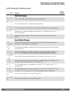
11
Check the gate, track and chain for any debris or cause for resistance. Check
the “ODS” setting on the control board.
pg. 8, 12,
26
12
Check that the gate can be moved manually with low resistance throughout its
full length of travel.
pg. 8, 17
13
Check the limit position.
pg. 20-21
14
Check that the cable for the Electronic Positioning Sensor for damage. Clean the
connection pins.
pg. 4
15 Check that the EMI cable is properly connected to the “EMI” Connector on the
control board.
pg. 4
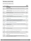
16
Check the LCD Display for Error Messages
pg. 40
17
Check that the cable from the Electronic Positioning Sensor is connected to the
“EPS2” port on the Control Board.
pg. 3-4
18
Check 4 Amp fuse on the control board
pg. 4
19
Manually adjust any setting on the Control Board to clear all wireless override
settings
20
Check for 24VAC out from the Toroidal Transformer and Power Harness
pg. 3, 18
21
Check the EMI Cable and contacts betwen the EMI Board and the VFlex Board
pg. 2, 4
?
The Control Board or EMI board may be damaged. Call Viking Technical Support
for further assistance