


- 5 -
www.vivotek.com
T: 886-2-22404099
F: 886-2-22404097
Installation
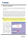
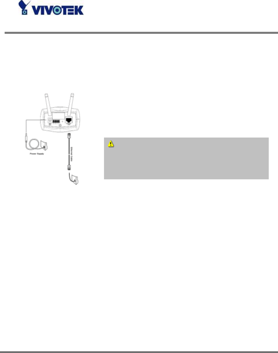
Hardware installation
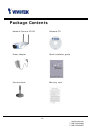
All necessary accessories can be found in the product
package except for the Ethernet cable that depends on the
user’s environment. The Ethernet cable should meet UTP
category 5 that cannot exceed 100 meters.
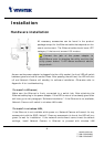
As soon as the power adapter is plugged into the utility socket, the front LED will switch
between green and red for several times. After passing the self-test, the LED will shut
off and Network Camera will standby for software installation. Otherwise refer to
Appendix A for troubleshooting.
To install in Ethernet,
Make sure the Ethernet is firmly connected to a switch hub. After attaching the
Ethernet cable plug in the power adapter. If the LED turns out to be steady green after
self-test, go to next paragraph “Software installation”. If the Ethernet is not available,
Network Camera will switch to wireless LAN mode.
To install in wireless LAN,
If the Ethernet is not available while power on, Network Camera will search for any
access point with the SSID “default”. Once any access point is found, the LED will turn
green to wait for installation. If the network environment cannot meet the default
settings, install Network Camera in Ethernet to proceed with wireless LAN
C onnect the
j
ack of the
p
ower ada
p
ter t
o
MiniAVServer
p
rior to
p
lu
gg
in
g
the utilit
y
end into th
e
utility power socket. It will reduce accidental electri
c
surge shock.