CAN Getting Started Guide www.xilinx.com 25
UG186 April 19, 2010
Demonstration Test Bench
Demonstration Test Bench
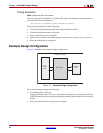
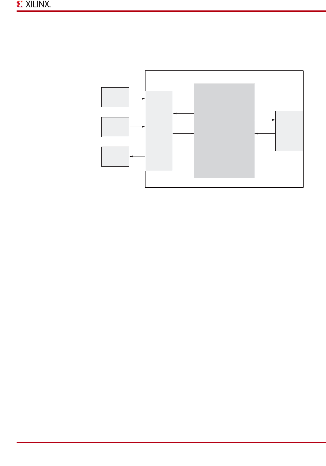
Figure 4-2 illustrates the demonstration test bench.
Test Bench Functionality
The demonstration test bench is a straightforward VHDL or Verilog file to exercise the
example design and the core itself.
The test bench consists of the following:
• Clock Generators
• Procedure to write to a Configuration Register memory location
• Procedure to read from a Configuration Register memory location
• Procedure to display the bits set in the Interrupt Status Register (ISR)
Core with No Acceptance Filtering
The demonstration test bench performs the following tasks:
• Input clock signals are generated.
• A reset is applied to the example design.
• The Baud Rate Prescalar register and Bit Timing registers are written to. These
registers are read from and the values read are compared with the values written.
• The Interrupt Enable Register is written to enable interrupts for TXBFLL and RXOK
bits. This register is read from and the value read is compared with the value written.
• The Mode Select Register is written to select Loop Back mode of operation. This
register is read from and the value read is compared with the value written.
• The Software Reset Register is written to enable CEN bit. This register is read from
and the value written is compared with the value read.
X-Ref Target - Figure 4-2
Figure 4-2: Demonstration Test Bench
Demonstration Test Bench
CAN Example Design
CAN Phy
IOBs
User
Interface
IOBs
Stimulus
Generator
Clock
Generator
Checker
CAN Core


